


CM6000 Install Guide
Alarm and Starter System
www.firstechonline.com | www.compustar.com
Copyright 2009 Firstech, LLC.
Page 12
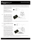
The new CM6 Series the Blade connector has a locking tab. Non-locking tab blade harnesses will work
but you MUST TAKE CARE TO NOT PLUG THE HARNESS IN UPSIDE DOWN. Make sure the two
notches on the top of the harness face the top (CM and barcode sticker side) of the brain. When looking at the
wire side of the harness the two notches must be at the top of the plug.
Blade system includes:
1. Blade-AL or Blade-TB (NOTE: These modules are blank and must be ashed on your computer.)
2. 20 Pin locking wiring harness
3. 3 Pin harness used in some installs
IMPORTANT: Install diagrams are not included and must be downloaded from www.idatalink.com/compustar.
When ashing the Blade you can use the Y-Cable OP500 end and not CM4 Series end. ADS and Firstech
recommends using the 4 pin RS232 cable to avoid confusion. Cartridge must be removed to ash the control
module rmware.
NOTE: The ADS-RNG C1, ADS-RNG C2, and ADS-RNG GM3 are not included and must be purchased sepa-
rately. The 20 pin Blade connector comes only with the Blade cartridge and not the CM6 control modules.
WARNING: Manufacturer or seller assumes no responsibility for any injuries and/or damages caused by
improper care of the product such as decomposition, conversion, and transform done by a user voluntarily.
WARNING: There should be no wiring routed around any pedals which can cause a driving hazard.
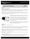
Wiring Descriptions CM6000
Connector 1 (CN1), 6-Pin
Pin 1 White – Accessory 12V positive (+) output. This wire must be connected to the vehicle accessory
/ HVAC blower motor wire. The proper wire will test 0V with the key in the off position, (+) 12V
while key is in the on position, 0V while cranking and back to (+) 12V when the key is returned to
the on position. This wire has a 25 amp fuse on it.
Pin 2 Yellow - Starter 12V positive (+) output. This wire is pre-wired to Pin 87a of the anti-grind/starter-kill
relay. This wire must be connected for remote start. The proper wire will test 0V with the key in the off
position, 0V while the key is in the on position and (+) 12V during crank.