


CM6000 Install Guide
Alarm and Starter System
www.firstechonline.com | www.compustar.com
Copyright 2009 Firstech, LLC.
Page 7
Placement and Use of Components CM6000
IMPORTANT: The placement and use of components are critical to the performance of this system.
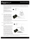
Antenna and Cable
Firstech antennas are calibrated for horizontal installation at the top of the windshield. The cable that connects
the antenna to the control module must be free from any pinches or kinks. Installing the antenna in areas other
than the windshield may adversely affect the effective transmitting distance of the remotes.
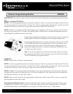
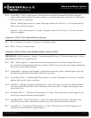
RPS-2 (Remote Paging Sensor)
The RPS-2 sensor is designed to be mounted on the inside of the windshield. Basic RPS functions do not re-
quire programming. There is a three position switch on the rear of the RPS-2. This adjusts the sensitivity of the
RPS-2. The larger the circle the more sensitive the knock is. The RPS-2 can now relock/rearm your vehicle.
Just knock 5 times without the ignition on and door open and it will rearm. T
o activate the RPS unlock / disarm
feature you must perform the following procedure:
STEP 1: Disarm/unlock the alarm. (Remotes must be programmed rst.)
STEP 2: Turn ignition key to the “on” position and the leave the driver’s door open.
STEP 3: Knock on the windshield in front of the RPS a total of 5 times (each time you knock the LED on the RPS will ash RED).
The LED will begin to ash rapidly in BLUE with successful completion of this step.
STEP 4: Enter the rst digit of the desired four-digit pass code by knocking on the windshield in front of the RPS the desired number
of times. For example, to enter 3, knock on the sensor 3 times (each time you knock the LED will ash RED) then wait.
STEP 5: The LED on the RPS will conrm your rst number by ashing BLUE slowly. Once the LED begins to ash rapidly in
BLUE, enter your second number by repeating step 4.
STEP 6: Repeat steps 4 & 5 to enter all four numbers.
STEP 7: Turn the ignition OFF. The RPS disarm/unlock feature is now programmed. Repeat steps 3 – 5 to enter your disarm/unlock
code.
**The rst two digits of the RPS unlock/disarm pass code will be the default pass code for the Secure Valet (you do not need to
program them independently).
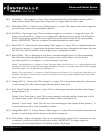
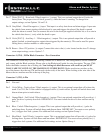
Secure Valet Switch
The optional Secure Valet Switch prevents the alarm from being put into valet mode through cycling the igni-
tion on/off ve times. The Secure Valet Switch is more secure than traditional toggle / valet switches because it
requires a two digit code. To program this feature you must perform the following procedures:
STEP 1: Turn on Option 3-10-III.
STEP 2: Turn ignition key to the “on” position.
STEP 3: Hold down the valet switch for 1.5 seconds. The LED on the valet switch will begin to ash rapidly with successful comple-
tion of this step.
STEP 4: Enter the rst digit of the desired two-digit pass code by depressing the switch the number of times that coordinates with the
desired rst number. For example, to enter 3, depress the switch 3 times, then wait.
STEP 5: The LED will conrm the rst number by ashing BLUE slowly. Once the LED begins to ash rapidly, enter your second
number by repeating step 4.
STEP 6: Turn the ignition off - the Secure Valet Switch is now programmed. Follow steps 3 – 5 to enter your Secure Valet code.
**The rst two digits of the RPS unlock/disarm pass code will be the default pass code for the Secure Valet (you do not need to
program them independently).