


CM6000 Install Guide
Alarm and Starter System
www.firstechonline.com | www.compustar.com
Copyright 2009 Firstech, LLC.
Page 13
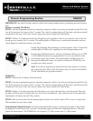
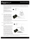
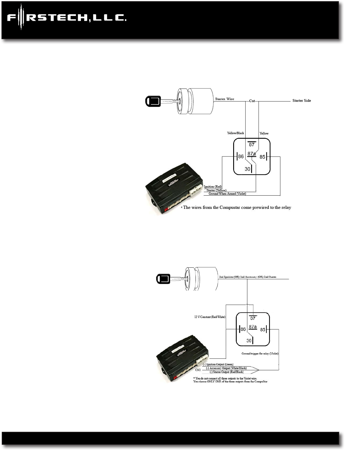
There are two wires coming off of the relay; yellow-black and yellow. To utilize the anti-grind or starter-
kill features, the vehicles starter wire must be cut in half, otherwise, cut the relay out of the harness and
connect the yellow (Pin 6) directly to the vehicles’ starter wire. The starter kill/anti grind relay has a thin
24 guage blue wire. This must be
connected to pin 1 (24 guage blue
wire) on Connector 3.
IMPORTANT: For anti-grind and
starter-kill applications, the yellow wire
goes to the starter side of the vehicles starter
wire and the yellow/black goes to the key
side.
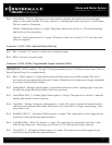
Pin 3 Green – Ignition 12V positive (+)
output and input. This wire must be
connected to the vehicles ignition
for remote start and valet/program
ming. The proper wire will test 0V
with the key in the off position, 12V
(+) while the key is in the on posi-
tion and 12V (+) during crank. This
pin also has a thin green wire that is
prewired to the starter kill relay. If you are not installing anti grind/starter kill, you do not need to con
nect the thin 24 guage green wire.
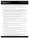
Pin 4 Black - Ground negative (-) input. This
wire must be connected to the vehicle’s
ground.
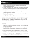
Pin 5 Red - Constant 12V positive (+) power
input. These two wires must be con
nected. The proper vehicle wire will test
(+) 12V at all times while the key is
in the off position, the on position and
during crank. Each wire has a 30 amp
fuse on it. An optional relay with a 14
guage red wire and 30 amp fuse is for
secondary ignition/accessory/starter
wires. The short violet wire on Pin 85
is the trigger input wire that determines
the (+) 12V output type of the long blue
wire on Pin 30. For example, connecting
the negative (-) Ignition output from Connector 3, to the short violet wire coming off of the relay, will
provide an additional (+) 12V Ignition output from the long blue wire.