


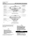
667 Size 80 and 100 Actuators
Instruction Manual
Form 1432
December 2007
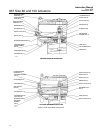
9
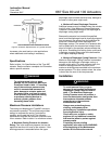
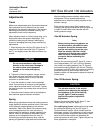
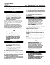
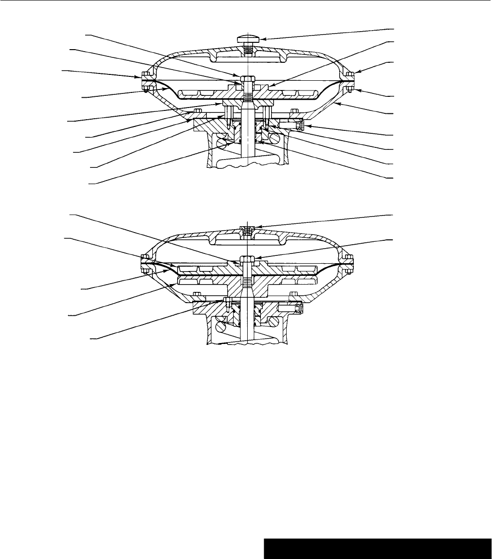
Figure 4. Size 80 Actuator Construction
CAP SCREW (KEY 12)
SPACER (KEY 2)
UPPER DIAPHRAGM
CASE (KEY 1)
DIAPHRAGM (KEY 3)
LOWER DIAPHRAGM
PLATE (KEY 71)
CAP SCREW (KEY 30)
GASKET (KEY 70)
TRAVEL STOP (KEY 84)
SEAL BUSHING (KEY 7)
VENT ASSEMBLY (KEY 17)
UPPER DIAPHRAGM
PLATE (KEY 4)
CAP SCREW (KEY 13)
HEX NUT (KEY 14)
LOWER DIAPHRAGM
CASE (KEY 64)
PIPE BUSHING (KEY 92)
SNAP RING (KEY 72)
O-RING (KEY 9)
O-RING (KEY 8)
SPACER (KEY 2)
UPPER DIAPHRAGM
PLATE (KEY 4)
DIAPHRAGM (KEY 3)
LOWER DIAPHRAGM
PLATE (KEY 71)
TRAVEL STOP (KEY 84)
PIPE BUSHING (KEY 78)
CAP SCREW (KEY 12)
STANDARD DIAPHRAGM CONSTRUCTION
TOP LOADED DIAPHRAGM CONSTRUCTION
50A8597-D
50A8599-C
C0772 / IL
(key 144), and secure using the cap screw (key 12).
Coat the cap screw threads with lithium grease
(key 237). Tighten the cap screw (key 12) to 544
NSm (400 lbfSft).
Note
Standard and top-loaded
constructions use the same key
numbers for parts. The parts look
different, but they use the same
assembly and disassembly sequence.
See figure 4, Size 80 Actuator
Construction.
10. Position the upper diaphragm casing (key 1) on
the diaphragm (key 3), and align the holes.
Note
When you replace actuator
diaphragms in the field, take care to
ensure the diaphragm casing cap
screws are tightened to the proper
load to prevent leakage, but do not
crush the material. Perform the
following tightening sequence with a
manual torque wrench for size 80 and
100 actuators.
CAUTION
Do not use lubricant on these cap
screws and nuts. Fasteners must be
clean and dry.
Overtightening the diaphragm casing
cap screws and nuts can damage the