


667 Size 80 and 100 Actuators
Instruction Manual
Form 1432
December 2007
7
D Disconnect any operating lines
providing air pressure, electric power,
or a control signal to the actuator. Be
sure the actuator cannot suddenly
open or close the valve.
D Use bypass valves or completely
shut off the process to isolate the
valve from process pressure. Relieve
process pressure from both sides of
the valve. Drain the process media
from both sides of the valve.
D Vent the power actuator loading
pressure and relieve any actuator
spring precompression.
D Use lock-out procedures to be
sure that the above measures stay in
effect while you work on the
equipment.
D The valve packing box may
contain process fluids that are
pressurized, even when the valve has
been removed from the pipeline.
Process fluids may spray out under
pressure when removing the packing
hardware or packing rings, or when
loosening the packing box pipe plug.
D Check with your process or safety
engineer for any additional measures
that must be taken to protect against
process media.
Size 80 Actuator Maintenance
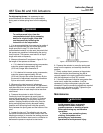
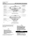
For size 80 actuators, refer to figure 4 for part names
and locations. Key number locations for size 80
actuators are shown in figure 6.
Disassembly
1. Isolate the control valve from the line pressure,
release pressure from both sides of the valve, and
drain the process media from both sides of the
valve. Shut off all pressure lines to the power
actuator, release all pressure from the actuator. Use
lock-out procedures to be sure that the above
measures stay in effect while you work on the
equipment.
2. Remove the tubing or piping from the connection
in the top of the spring case adaptor (key 89).
3. If the actuator has a handwheel, rotate the
handwheel to relieve all spring compression.
4. Remove the cover band (key 87). Insert a steel
rod of approximately 12.7 mm (1/2-inch) diameter
into a hole in the spring adjustor (key 74), and rotate
the spring adjustor from right to left until spring
compression is relieved.
WARNING
To avoid personal injury due to the
sudden, uncontrolled movement of
parts, do not loosen the cap screws on
the stem connector (key 31) when
spring force is applied.
5. If necessary, the entire actuator assembly may
be removed from the valve by unscrewing the cap
screws from the stem connector (key 31) and
removing actuator-to-bonnet bolting.
6. Unscrew the diaphragm casing cap screws and
nuts (keys 13 and 14), and lift off the upper
diaphragm casing (key 1).
7. Unscrew the diaphragm cap screw (key 12),
remove the spacer, upper diaphragm plate,
diaphragm, and lower diaphragm plate (keys 2, 4, 3,
and 71).
Note
Standard and top-loaded
constructions use the same key
numbers for parts. The parts look
different, but they use the same
assembly and disassembly sequence.
See figure 4, Size 80 Actuator
Construction for location of parts.
8. Unscrew the cap screws (key 30), and remove
the lower diaphragm casing (key 64).
9. For actuators without a snubber:
a. Unscrew the spring case adaptor cap screws
and nuts (keys 90 and 91), and remove the
adaptor (key 89) from the actuator.
b. Remove the snap ring and seal bushings
(keys 72 and 7). Inspect, and if necessary, obtain
a replacement seal bushing (key 7). Replace the
seal bushing O-rings (keys 8 and 9) as required.
Lubricate with lithium grease (key 237) lubricant.
c. Remove the actuator spring (key 18). Unscrew
the cap screws from the stem connector (key 31),
and remove the stem connector. Remove the
stem (key 144) and attached spring adjustor,
thrust bearing, and spring seat (keys 74, 86,
and 19).