


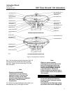

667 Size 80 and 100 Actuators
Instruction Manual
Form 1432
December 2007
8
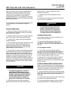
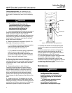
10. For actuators with a snubber (see figure 8):
WARNING
To avoid personal injury due to the
sudden, uncontrolled movement of
parts, ensure the actuator spring is not
under compression before removing
the travel stop.
a. Remove the travel stop (key 84). Be certain
there is not compression in the actuator spring
(key 18). If the actuator was removed from the
valve, secure the stem connector (key 31) to the
actuator stem (key 144) to prevent the stem from
turning while unscrewing the stem and piston
assembly (key 23).
b. Using a wrench on the wrench flats near the
top of the stem and piston assembly, unscrew the
stem and piston assembly from the actuator
stem.
c. Unscrew the cap screws (key 106), and
remove the cylinder (key 93) and attached parts.
11. To disassemble snubber:
a. Remove the retaining rings, cylinder heads,
and stem and piston assembly (keys 95, 94,
and 23).
b. Replace packing and O-rings (keys 118, 119,
96, 107, and 120).
c. Unscrew the spring case adaptor cap screws
and nuts (keys 90 and 91), and remove the
adaptor (key 89) from the actuator.
12. Remove the actuator spring and spring seat
(keys 18 and 19).
13. Unscrew the cap screws and nuts (keys 88
and 91), and remove the spring case (key 85).
Note
In figure 8, the cap screws (key 88) on
units with side-mounted handwheels
do not use hex nuts (key 91).
14. Remove the spring adjustor (key 74) and the
attached thrust bearing (key 86).
15. Remove the cap screws (key 252), yoke
bushing retainer (key 251), 2 halves of the split yoke
bushing (key 249), and yoke bushing holder
(key 250).
16. Refer to the size 80 actuator assembly
procedures. Carefully clean and inspect all parts,
and obtain any replacement parts required for
reassembly.
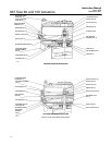
Assembly
See figure 4, Size 80 Actuator Construction for
location of parts.
1. Coat the threads of the stem (key 144) with
lithium grease lubricant (key 237). Install the spring
adjustor (key 74) and thrust bearing. Pack the
bearing (key 86) with lithium grease lubricant.
2. Mount the spring case (key 85) to the yoke
(key 73) using cap screws and hex nuts (keys 88
and 91).
Note
Units with a side-mounted handwheel
do not use hex nuts (key 91).
3. Install the spring adjustor, thrust bearing, and
spring seat (keys 74, 86 and 19) onto the actuator
stem (key 144). Slide the stem into the spring case
(key 85).
4. Align the spring seat (key 19) on the spring
adjustor (key 74), and slide the actuator spring
(key 18) squarely onto the spring seat.
5. Mount the spring case adaptor (key 89) to the
spring case (key 85) using cap screws and hex nuts
(keys 90 and 91).
6. For actuators with a snubber (see figure 8),
install the cylinder (key 93) and attached parts with
cap screws (key 106). Slide the stem and piston
assembly (key 23) into the cylinder and thread onto
the actuator stem (key 144). Attach the travel stop
(key 84), if one is used, to the stem and piston
assembly.
7. For actuators without a snubber, install the
seal bushing (key 7) into the spring case adaptor
(key 89) followed by the snap ring (key 72). Replace
the seal bushing O-rings (keys 8 and 9) as required.
8. Coat the gasket (key 70) with lithium grease
lubricant (key 237). Position the lower diaphragm
casing (key 64) on the spring case adaptor, and
secure with cap screws (key 30).
9. Mount the lower diaphragm plate, diaphragm,
upper diaphragm plate, and, if used, spacer
(keys 71, 3, 4, and 2) on the actuator stem