


667 Size 80 and 100 Actuators
Instruction Manual
Form 1432
December 2007
3
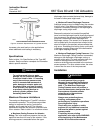
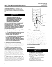
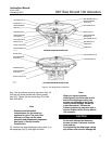
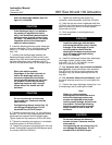
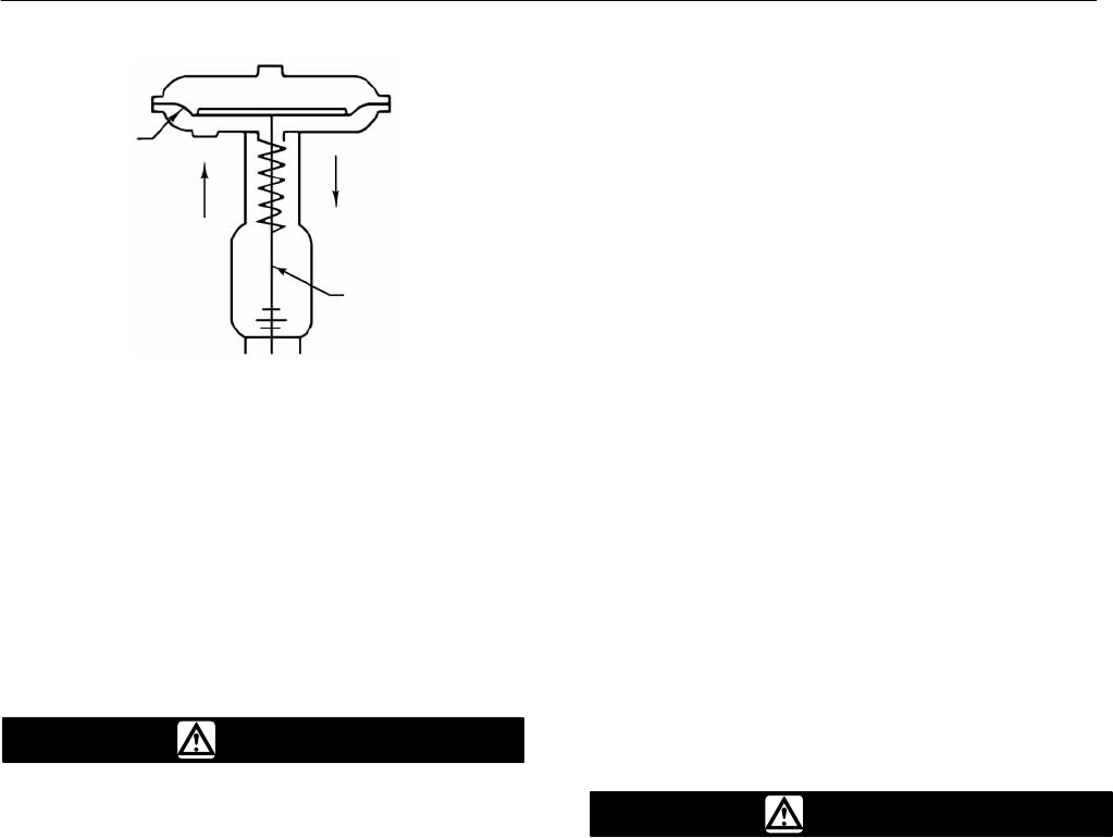
Figure 2. Schematic Representation of Type 667 Actuator
DIAPHRAGM
AIR
LIFTS
SPRING
PUSHES
DOWN
ACTUATOR
STEM
TYPE 667 REVERSEĆACTING DIAPHRAGM ACTUATOR
AF3833-A
A6127 / IL
increases valve seat load on valve applications
where additional seat-loading is necessary.
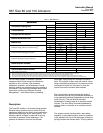
Specifications
Refer to table 1 for Specifications of the Type 667
actuator. See the actuator nameplate for information
about a specific actuator.
WARNING
To avoid personal injury or parts
damage, do not exceed the Maximum
Pressures listed in table 1. Exceeding
any of the maximum pressures can
result in uncontrolled movement of
parts, damage to actuator parts and
the control valve, and loss of control
of the process. Use pressure-limiting
or pressure-relieving devices to
prevent cylinder pressure from
exceeding these limits.
Maximum Pressure Limitations
The casing and diaphragm of Type 667 actuators
are pressure operated. This air pressure provides
energy to compress the spring, to stroke the
actuator, and to seat the valve. The following
explanations describe the maximum pressure limits
for an actuator. Refer to table 1 for maximum values.
D Maximum Casing Pressure for Actuator
Sizing: This is the maximum pressure that can be
applied at less than full travel of the actuator. If this
stroking pressure is exceeded before the upper
diaphragm plate contacts the travel stop, damage to
the stem or other parts might result.
D Maximum Excess Diaphragm Pressure:
Additional pressure may be added when the actuator
is at full travel. If the Maximum Excess Diaphragm
Pressure is exceeded, damage to the diaphragm or
diaphragm casing might result.
Because the actuator has traveled its specified
travel, and the diaphragm head is physically stopped
from movement, the energy from any additional air
pressure is transmitted to the diaphragm and
diaphragm casings. The amount of air pressure that
can be added once the actuator has traveled to the
stops is limited by the resultant adverse effects that
may occur. Exceeding this limiting factor could result
in leakage or casing fatigue due to the deformation
of the upper diaphragm casing.
D Maximum Diaphragm Casing Pressure: If the
Maximum Diaphragm Casing Pressure is exceeded,
damage to the diaphragm, diaphragm casing, or
actuator might result. For some actuator sizes, the
maximum casing pressure is the sum of the
maximum stroking pressure added to the maximum
excess pressure. For other actuator sizes, the value
is lower than the sum of the two pressures.
Installation
WARNING
To avoid personal injury or parts
damage, do not exceed the Maximum
Diaphragm Casing Pressure listed in
table 1. The Maximum Diaphragm
Casing Pressure must not produce a
force on the actuator stem greater than
the maximum allowable actuator
output thrust or the maximum
allowable stem load.
Always wear protective gloves,
clothing, and eyewear when
performing any installation operations
to avoid personal injury.
Check with your process or safety
engineer for any additional measures
that must be taken to protect against
process media.
If installing into an existing
application, also refer to the WARNING
at the beginning of the Maintenance
section in this instruction manual.