


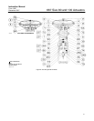

667 Size 80 and 100 Actuators
Instruction Manual
Form 1432
December 2007
17
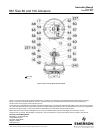
worm shaft (key 51). Thread the handwheel cap
(key 127) onto the worm shaft.
6. Pack the two thrust bearings (key 43) with lithium
grease lubricant. Install one thrust bearing; then
install the worm gear (key 44), followed by the
second thrust bearing and the bearing and gear
retainer (key 45).
7. The lower sleeve (key 123) has two screw holes
in one end. Coat the sleeve threads with lithium
grease lubricant, slide the end of the lower sleeve
with the holes into the thrust bearing (key 43), turn
the handwheel, and feed the sleeve through the
worm gear. Continue turning the handwheel until the
lower sleeve protrudes from the gear case. Fasten
the travel stop indicator (key 126) to the sleeve with
two machine screws (key 79).
8. Install the key (key 122) on the retaining flange
(key 134).
9. Install the retaining flange (key 134) so that the
key engages the slot in the lower sleeve. Secure the
retaining flange with the cap screws (key 136).
10. Adjust the set screws (key 121) to eliminate free
play in the bearings.
Note
Overtightening the set screws will
make handwheel operation difficult.
11. Coat the spring adjustor (key 74) threads with
lithium grease lubricant and install it over the lower
sleeve.
12. Pack the thrust bearing (key 86) with lithium
grease lubricant, and install it on the spring adjustor
(key 74) as shown in figure 8.
13. Slide the spring case (key 85) into position, and
secure with cap screws (key 88).
14. Complete steps 3 through 16 of the Assembly
procedure in the Size 80 Actuator Maintenance
section.
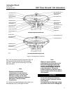
Size 80 Hydraulic Snubber
The size 80 Type 667 is available with a hydraulic
snubber, as shown in figure 8, to aid vertical stability
of the actuator stem movement. The snubber is
adjusted by rotating the adjusting screws (key 104,
figure 8) counterclockwise out of the reservoir
(key 99, figure 8) to increase damping action and
clockwise to decrease damping action. The adjusting
screw on the right (the top one of the two adjusting
screws in section B-B of figure 8) regulates
downward damping action, and the screw on the left
regulates upward damping action.
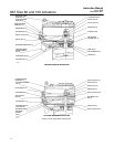
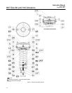
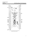
Size 100 Top-Mounted Handwheel
(Adjustable Up Travel Stop)
Key numbers are shown in figure 9.
A top-mounted handwheel assembly is normally
used as an adjustable-up travel stop to limit full
retraction of the actuator stem. Clockwise rotation of
the handwheel (key 58) moves the actuator stem
(key 144) downward. Counterclockwise rotation will
compress the spring and move the actuator stem
upward.
Instructions are given below for complete
disassembly and assembly. Disassemble only as far
as necessary to accomplish the required
maintenance; then, begin the assembly at the
appropriate step.
Disassembly
1. Isolate the control valve from the line pressure,
release pressure from both sides of the valve, and
drain the process media from both sides of the
valve. If using a power actuator, also shut off all
pressure lines to the power actuator, release all
pressure from the actuator. Use lock-out procedures
to be sure that the above measures stay in effect
while you work on the equipment.
2. Bypass the control valve. Reduce the loading
pressure to atmospheric (refer to the Maintenance
section), and remove the tubing or piping from the
diaphragm casing.
3. Unscrew the cap screws (key 54), and remove
the gear case cover (key 53).
4. Loosen the set screws (key 52) in the front and
back worm retainers (keys 48 and 49) and the
handwheel (key 58).
5. Remove the retaining ring (key 60), and remove
the handwheel.
6. Remove front and back worm retainers (keys 48
and 49) and the bearings (key 50).
7. Remove the worm shaft (key 51).
8. Remove the power screw assembly (key 46) by
placing a wrench on the double hex nuts (key 47)
and unscrew the assembly from the actuator stem
extension (key 36). The bearing and gear retainer,
thrust bearing, and worm gear (keys 45, 43, and 44)
will come out with the power screw.