


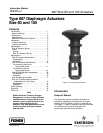

667 Size 80 and 100 Actuators
Instruction Manual
Form 1432
December 2007
4
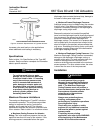
When an actuator and valve are shipped together,
the actuator is normally mounted on the valve.
Follow the valve instructions when installing the
control valve in the pipeline. If the actuator is
shipped separately or if it is necessary to mount the
actuator on the valve, perform the following Actuator
Mounting procedures.
For information on mounting valve positioners, refer
to the appropriate valve positioner instruction
manual.
Actuator Mounting
1. Mount the actuator on the valve bonnet. Insert
the cap screws and tighten the hex nuts, securing
the actuator to the bonnet.
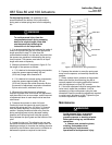
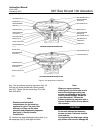
2. Screw the valve stem jam nuts (key 69, figures 6
and 7) all the way onto the valve stem threads.
3. Connect an air supply to the lower diaphragm
casing connection.
4. For push-down-to-close valves, be sure the valve
plug is on its seat. Reduce loading pressure to
ensure that the actuator stem is fully extended.
Apply slight loading pressure to retract the stem
approximately 3.2 mm (1/8-inch).
5. For push-down-to-open valves, apply pressure to
ensure that the actuator stem is fully retracted. Be
sure the valve plug is on its seat. On large valve
sizes, this may require the use of a pry bar inserted
through the valve body line opening. If the valve is
installed in a pipeline, the bottom flange (if one is
used) can be removed and the valve plug pushed to
the seat from the bottom opening. Reduce actuator
loading pressure to extend the stem approximately
3.2 mm (1/8-inch).
CAUTION
Incomplete engagement of either the
valve stem or actuator stem in the
stem connector can result in stripped
threads or improper operation. Be sure
that the length of each stem clamped
in the stem connector is equal to or
greater than the diameter of that stem.
6. Clamp the actuator and valve plug stems
between the two stem connector halves (key 31,
figures 6 and 7). Insert and tighten the stem
connector cap screws.
7. Thread the stem locknuts against the stem
connector.
8. Align the travel indicator scale (key 32, figures 6
and 7) to show valve position.
WARNING
To avoid personal injury due to the
sudden, uncontrolled movement of
parts, do not loosen the cap screws
when the stem connector has spring
or loading pressure force applied to it.
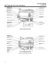
Loading Connection
Key number locations are shown in figures 6 and 7,
unless otherwise directed.
1. Connect the loading pressure piping to the
connection in the size 80 spring case adaptor
(key 89) or in the size 100 lower diaphragm casing
(key 67).
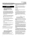
For top-loaded actuators
1. For size 80, remove the the pipe bushing
(key 78), and connect the loading pressure piping in
its place. For size 100, remove the hex bushing
(key 62) from the upper casing (key 1), and connect
the top loading pressure piping in its place.
2. Remove the 1/4-inch bushing (key 92, figure 6;
key 62, figure 7) to increase connection size, if
necessary. The connection can be made with either
piping or tubing.
3. Keep the length of tubing or piping as short as
possible to avoid transmission lag in the control
signal. If an accessory (such as a volume booster or
valve positioner) is used, be sure that the accessory
is properly connected to the actuator. Refer to the
positioner instruction manual as necessary.
4. Cycle the actuator several times to check that the
valve stem travel is correct and that the travel occurs
when the correct pressure range is applied to the
diaphragm.
5. If valve stem travel is incorrect, refer to the Travel
procedure in the Adjustments section.
6. If the spring pressure range is incorrect, refer to
the Spring procedure in the Adjustments section.