


667 Size 80 and 100 Actuators
Instruction Manual
Form 1432
December 2007
13
spring interferes with installation of
the lower diaphragm casing, reposition
the spring by rotating the adjusting
nut (key 25).
4. Install the lower diaphragm casing, and secure it
by tightening the four hex nuts.
5. Lubricate the seal bushing O-rings (keys 8 and 9)
and the seal bushing (key 7) with lithium grease
lubricant. Install the seal bushing O-rings, seal
bushing, and seal bushing retainer (keys 8, 9, 7
and 10) and secure with the cap screws (key 11).
6. Install the diaphragm backup plate, diaphragm
retainer, diaphragm, upper diaphragm plate, and
washer (keys 6, 5, 3, 4, and 37) on the actuator stem
(key 144).
CAUTION
Install the diaphragm with the fabric
side facing away from the spring.
Smooth the edge of the diaphragm to
avoid wrinkling and be careful that the
diaphragm fold does not get pinched
when the upper diaphragm casing
(key 1) is installed.
CAUTION
If the diaphragm (key 3) is installed so
air pressure is applied to the fabric
side, it will immediately delaminate the
sealing surface (smooth surface) from
the fabric. The delamination can cause
immediate failure of the diaphragm’s
ability to retain pressure.
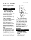
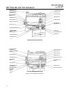
7. For actuators with a top-mounted handwheel,
screw the actuator stem extension (key 36, figure 9)
as far as it will go into the actuator stem connector
(key 42, figure 9) before tightening the hex nut
(key 28, figure 9).
8. For actuators without a top-mounted
handwheel, Install the hex nut (key 241) and
tighten, install the jam nut (key 24) and tighten so
that it locks the hex nut key 24 in place. Install the
travel stop (key 12).
9. Position the upper diaphragm casing (key 1) on
the diaphragm (key 3) and align the holes.
Note
When you replace actuator
diaphragms in the field, take care to
ensure the diaphragm casing cap
screws are tightened to the proper
load to prevent leakage, but not crush
the material. Perform the following
tightening sequence with a manual
torque wrench for size 80 and 100
actuators.
CAUTION
Do not use lubricant on these cap
screws and nuts. Fasteners must be
clean and dry.
Overtightening the diaphragm casing
cap screws and nuts can damage the
diaphragm. Do not exceed 68 NSm (50
lbfSft) torque.
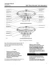
10. Insert the cap screws (key 13) into the upper
diaphragm casing, and tighten the hex nuts (key 14)
in the following manner. The first four hex nuts
tightened should be diametrically opposed and 90
degrees apart. Tighten these four hex nuts to 34
NSm (25 lbfSft).
11. Tighten the remaining hex nuts in a clockwise,
crisscross pattern to 34 NSm (25 lbfSft).
12. Repeat this procedure by tightening the four hex
nuts, diametrically opposed and 90 degrees apart, to
a torque of 68 NSm (50 lbfSft).
13. Tighten the remaining hex nuts in a clockwise,
crisscross pattern to 68 NSm (50 lbfSft).
14. After the last hex nut is tightened to 68 NSm (50
lbfSft), all of the hex nuts should be tightened again
to 68 NSm (50 lbfSft) in a circular pattern around the
bolt circle.
15. Once completed, no more tightening is
recommended.
16. For actuators with a top-mounted handwheel
(see figure 9), mount the gear case assembly
(key 41) on the actuator using the cap screws
(key 54). Install the hex nuts (key 47) and travel stop
cap screw (if used) on the actuator stem extension
(key 36). Install the gear case cover (key 53) with
the cap screws.
17. Mount the actuator on the valve, and secure
with the actuator-to-bonnet bolting. Refer to the
Installation section to connect the actuator stem to
the valve plug stem.