


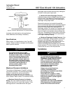

667 Size 80 and 100 Actuators
Instruction Manual
Form 1432
December 2007
11
These instructions outline the
procedure required to decrease high
spring compression.
Loosen the jam nut (key 26), and rotate the adjusting
nut (key 25) until spring compression is relieved.
3. Remove the pressure tubing or piping from the
top of the diaphragm casing.
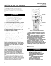
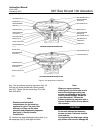
4. For actuators with a top-mounted handwheel
(see figure 9), rotate the handwheel (key 58)
clockwise as far as it will go, unscrew the cap
screws (key 54), and remove the gear case cover
(key 53). Remove the travel stop cap screw, if one is
used, from the actuator stem extension (key 36), and
unscrew the hex nuts (key 47). Unscrew the cap
screws that attach the gear case assembly (key 41)
to the actuator, and remove the gear case assembly.
5. If necessary, remove the actuator from the valve
by separating the stem connector (key 31) and
removing the actuator-to-bonnet bolting. Separate
the stem connector by loosening the stem locknuts
(key 69) and unscrewing the four cap screws.
Note
If the actuator has been removed from
the valve, ensure that it is in the
vertical position. Then, block the
actuator stem (key 144) to support the
weight of the actuator stem, spring
seat and spring (keys 144, 19, and 18).
This will facilitate removal of the nut
(key 24) or actuator stem connector
(key 31, figure 8).
For Actuators Without the
Top-Loaded Option
Disassembly
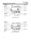
Part names and locations are shown in figure 5.
Size 100 actuator key number locations are shown in
figure 7.
1. Unscrew the diaphragm casing cap screws and
nuts (keys 13 and 14) and remove the upper
diaphragm casing.
2. For actuators without a top-mounted
handwheel, unscrew and remove the travel stop
cap screw (key 12), if one is used, and the hex nut
(key 24).
3. For actuators with a top-mounted handwheel
(see figure 9), remove the hex nut, actuator stem
extension, and actuator stem connector
(keys 28, 36, and 42).
4. Remove the washer, upper diaphragm plate,
diaphragm, diaphragm retainer, and backup plate
(keys 37, 4, 3, 5 and 6).
5. Unscrew the six cap screws (key 11), and remove
the seal bushing retainer (key 10). Remove the seal
bushing (key 7).
WARNING
To avoid personal injury and property
damage from the sudden release of
spring load, be sure that all spring
load is removed from the actuator
lower diaphragm casing.
6. Unscrew the four hex nuts that secure the lower
diaphragm casing to the yoke assembly (key 67),
and remove the lower diaphragm casing. Replace
the yoke assembly O-rings (key 70) as necessary.
7. The actuator spring (key 18) and stem (key 144)
can now be removed if necessary. Be sure to
disconnect the stem connector (key 31) before
removing the stem.
8. Refer to the following Assembly procedures.
Carefully clean and inspect all parts, or obtain
replacement parts required for reassembly.
Assembly
1. If the actuator stem (key 144, figure 7) was
removed, lubricate the threads on the stem with
lithium grease lubricant (key 237).
2. On the actuator stem, assemble the hex nuts,
thrust bearing, and spring seat (keys 26, 25, 86,
and 19) to the stem. Be certain that the thrust
bearing race with the larger inside diameter faces
the spring seat. Rotate the adjusting nut (key 25) to
position the spring seat 305 mm (12 inches) from the
end of the stem.
3. Install the actuator stem assembly into the yoke
assembly (key 67). Place a support under the stem
to position the lower end of the stem 254 mm (10
inches) above the bottom surface of the actuator
(actuator-to-bonnet joint).
Note
When installing lower diaphragm
casing, install the O-rings (key 70) into
the grooves found in the lower
diaphragm casing before placing the
casing on the yoke assembly. If the