


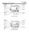

667 Size 80 and 100 Actuators
Instruction Manual
Form 1432
December 2007
16
18. Insert the cap screws (key 13) into the upper
diaphragm casing (key 1), and finger tighten the
screws.
19. Tighten the cap screws (key 13) in the following
manner. The first four cap screws tightened should
be diametrically opposed and 90 degrees apart.
Tighten these four cap screws to 34 NSm (25 lbfSft).
20. Tighten the remaining cap screws in a
clockwise, crisscross pattern to 34 NSm (25 lbfSft).
21. Repeat this procedure by tightening the four cap
screws, diametrically opposed and 90 degrees apart,
to a torque of 68 NSm (50 lbfSft).
22. Tighten the remaining cap screws in a
clockwise, crisscross pattern to 68 NSm (50 lbfSft).
23. After the last cap screw is tightened to 68 NSm
(50 lbfSft), all of the cap screws should be tightened
again to 68 NSm (50 lbfSft) in a circular pattern
around the bolt circle.
24. Once completed, no more tightening is
recommended.
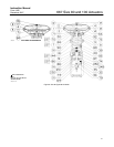
25. For actuators with a top-mounted handwheel
(see figure 9), mount the gear case assembly
(key 41) on the actuator using cap screws (key 54).
Install the hex nuts (key 47) and travel stop cap
screw (if used) on the actuator stem extension
(key 36). Install the gear case cover (key 53) with
cap screws.
26. Mount the actuator on the valve, and secure
with the actuator-to-bonnet bolting. Refer to the
Installation section to connect the actuator stem to
the valve plug stem.
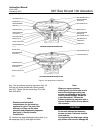
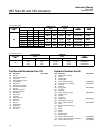
Size 80 Side-Mounted Handwheel
The side-mounted handwheel assembly (figure 8) is
normally used as a manual operator. The handwheel
can be mounted in either of two position orientations
so that, regardless of valve plug action,
counterclockwise rotation always opens the valve.
The assembly is a continuously connected type with
an indicator to show neutral position. By rotating the
handwheel away from neutral, the handwheel can be
used to limit travel in either direction, but not both
directions at the same time.
A grease fitting is provided on the gear box for
periodic gear lubrication with a general purpose
grease.
Instructions are given below for complete
disassembly and assembly. Perform the
disassembly only as far as necessary to accomplish
the required maintenance; then, begin the assembly
at the appropriate step.
Key number location are shown in figure 8.
Disassembly
1. Complete steps 1 through 16 of the Disassembly
portion of the Size 80 Actuator Maintenance section.
2. Unscrew the cap screws (key 88), and remove
the spring case (key 85). Unscrew the cap screws
(key 136), and remove the retaining flange
(key 134). Do not lose the key (key 122).
3. Unscrew two screws (key 79), and remove the
travel stop indicator (key 126).
4. Turn the handwheel (key 58) to raise the lower
sleeve. Continue turning the handwheel until the
lower sleeve is free of the worm gear (key 44). Lift
out the lower sleeve, bearing and gear retainer,
thrust bearing, and worm gear (keys 123, 45, 43,
and 44).
5. The worm shaft (key 51) and associated parts
can be removed in order to replace or lubricate
them. First, remove the handwheel cap (key 127)
and the handwheel (key 58). Do not lose the small
ball or spring (keys 141 and 142).
6. Loosen the two set screws and unscrew the two
worm retainers (keys 48 and 49). The ball bearings
(key 50) will come out with the retainers. Remove
the worm shaft (key 51).
Assembly
1. Pack the ball bearings (key 50) with lithium
grease lubricant (key 237), and insert one ball
bearing in the back worm retainer (key 48).
2. Thread the back worm retainer and ball bearing
(keys 48 and 50) into the gear case. Align the set
screw slot in the worm retainer with the set screw
hole in the gear case, insert the set screw, and
tighten.
3. Coat the worm shaft (key 51) threads with lithium
grease lubricant, and slide the shaft into the gear
case (key 41) so that the end of the shaft fits snugly
in the back worm retainer.
4. Insert the bearing in the front worm retainer
(key 49), and thread the retainer and ball bearing
into the gear case. Align the set screw slot in the
retainer with the set screw hole in the gear case,
insert the set screw, and tighten.
5. Put the spring and ball (keys 142 and 141) in the
handwheel (key 58). Slide the handwheel onto the