


667 Size 80 and 100 Actuators
Instruction Manual
Form 1432
December 2007
2
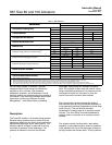
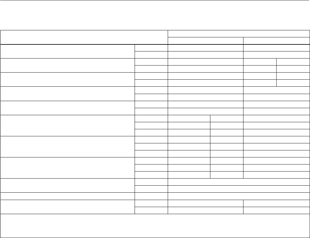
Table 1. Specifications
SPECIFICATION
ACTUATOR SIZE
SPECIFICATION
80 100
Nominal Effective Diaphragm Area
cm
2
1761 2902
Nominal Effective Diaphragm Area
inch
2
273 450
Yoke Boss Diameters
mm 127 127 178
Yoke Boss Diameters
inch 5 5H
(1)
7
Acceptable Valve Stem Diameters
mm 25.4 or 31.8 31.8 50.8
Acceptable Valve Stem Diameters
inch 1 or 1-1/4 1-1/4 2
Maximum Allowable Output Thrust
N 62,942 200,170
Maximum Allowable Output Thrust
lb 14,150
(2)
45,000
Maximum Travel
mm 76 102
Maximum Travel
inch 3 4
Cast Iron Steel
Maximum Casing Pressure for Actuator Sizing
(3)
bar 3.1 4.9 6.9
Maximum
Casing
Pressure
for
Actuator
Sizing
psig 45 70 100
Cast Iron Steel
Maximum Excess Diaphragm Pressure
(4)
bar 1.4 1.4 1.7
Maximum
Excess
Diaphragm
Pressure
psig 20 20 25
Cast Iron Steel
Maximum Diaphragm Casing Pressure
(5)(6)
bar 4.1 5.5 7.9
Maximum
Diaphragm
Casing
Pressure
psig 60 80 115
Material Temperature Capabilities
_C
–40 to 82
Material Temperature Capabilities
_F
–40 to 180
Pressure Connections 1/4 NPT internal
Approximate Weights Without Handwheel
kg 284 544
Approximate Weights Without Handwheel
lb 626 1200
1. Heavy actuator-to-bonnet bolting.
2. 88,075 N (19,800 lb) for steel construction.
3. Maximum diaphragm casing pressure that can be applied to cause travel stop contact. Indicated pressure must not be exceeded at less than full travel.
4. Maximum additional diaphragm casing pressure that can be applied after the travel stop cap screw contacts the upper diaphragm casing.
5. The sum of the pressure required to stroke the valve fully and the excess pressure added when the actuator is against the stop must not exceed these values.
6. This maximum casing pressure is not to be used for normal operating pressure. Its purpose is to allow for typical regulator supply settings and/or relief valve tolerances.
Do not install, operate, or maintain Type 667
actuators without first D being fully trained and
qualified in valve, actuator, and accessory
installation, operation, and maintenance, and D
carefully reading and understanding the contents of
this manual. If you have any questions about these
instructions, contact your Emerson Process
Managementt sales office before proceeding.
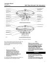
Description
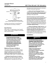
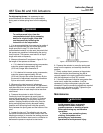
The Type 667 actuator is a reverse-acting actuator.
Reverse-acting actuators use air action to lift the
diaphragm (away from the valve), and spring action
opposes the diaphragm action (see figure 2). The
actuator position changes in response to varying
controlled air pressure to the diaphragm. If air
pressure is reduced or lost from the actuator
diaphragm, spring action will extend the actuator
stem. The actuator is often used with control valves
using a pneumatic positioner for air pressure control,
and where fail action will fully open or close the
control valve as the actuator stem extends.
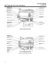
Also, the actuator can be furnished with either a
side-mounted (size 80 only) handwheel assembly or
a top-mounted handwheel (adjustable up travel stop)
(size 100 only). The size 80 side-mounted
handwheel is normally used as an auxiliary manual
actuator. The size 100 top-mounted handwheel is
used as either a travel stop or an auxiliary manual
actuator.
The actuator can be furnished with a top-loading
capability. A top-loaded actuator allows air pressure
to be applied to the top of the diaphragm, aiding the
spring to extend the actuator stem. This air pressure