


667 Size 80 and 100 Actuators
Instruction Manual
Form 1432
December 2007
10
diaphragm. Do not exceed 68 NSm (50
lbfSft) torque.
11. Insert the cap screws (key 13) into the
diaphragm casing, and tighten the hex nuts (key 14)
in the following manner. The first four hex nuts
tightened should be diametrically opposed and 90
degrees apart. Tighten these four hex nuts
to 34 NSm (25 lbfSft).
12. Tighten the remaining hex nuts in a clockwise,
crisscross pattern to 34 NSm (25 lbfSft).
13. Repeat this procedure by tightening four hex
nuts, diametrically opposed and 90 degrees apart, to
a torque of 68 NSm (50 lbfSft).
14. Tighten the remaining hex nuts in a clockwise,
crisscross pattern to 68 NSm (50 lbfSft).
15. After the last hex nut is tightened to 68 NSm (50
lbfSft), all of the hex nuts should be tightened again
to 68 NSm (50 lbfSft) in a circular pattern around the
bolt circle.
16. Once completed, no more tightening is
recommended.
17. For size 80 actuators without a manual operator,
slide the following parts over the bottom of the stem;
yoke bushing holder (key 250), two split yoke
bushings (key 249), and yoke bushing retainer
(key 251). Secure into place with 4 cap screws
(key 252). Before inserting the bushing halves,
lightly coat with lithium grease (key 237) lubricant.
18. Mount the actuator on the valve in accordance
with the procedures in the Installation section.
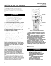
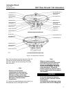
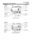
Size 100 Actuator Maintenance
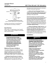
For size 100 actuators, refer to figure 5 for part
names and locations. Key number locations for Size
100 actuators are shown in figure 7.
WARNING
Avoid personal injury or property
damage from sudden release of
process pressure or bursting of parts.
Before performing any maintenance
operations:
D Always wear protective gloves,
clothing, and eyewear when
performing any maintenance
operations to avoid personal injury.
D Disconnect any operating lines
providing air pressure, electric power,
or a control signal to the actuator. Be
sure the actuator cannot suddenly
open or close the valve.
D Use bypass valves or completely
shut off the process to isolate the
valve from process pressure. Relieve
process pressure from both sides of
the valve. Drain the process media
from both sides of the valve.
D Vent the power actuator loading
pressure and relieve any actuator
spring precompression.
D Use lock-out procedures to be
sure that the above measures stay in
effect while you work on the
equipment.
D The valve packing box may
contain process fluids that are
pressurized, even when the valve has
been removed from the pipeline.
Process fluids may spray out under
pressure when removing the packing
hardware or packing rings, or when
loosening the packing box pipe plug.
D Check with your process or safety
engineer for any additional measures
that must be taken to protect against
process media.
1. Isolate the control valve from the line pressure,
release pressure from both sides of the valve, and
drain the process media from both sides of the
valve. If using a power actuator, also shut off all
pressure lines to the power actuator, release all air
pressure from the actuator. Use lock-out procedures
to be sure that the above measures stay in effect
while you work on the equipment.
2. Remove the shroud plate (key 65) by removing
the cap head screws (key 66).
a. For small spring force, loosen the jam nut
(key 26), and rotate the adjusting nut (key 25)
until spring compression is relieved.
b. For high spring force:
Note
To relieve spring compression when
high spring forces exist, refer to the
Spring section, and follow the
instructions given for size 100
actuators with high spring force.