


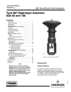

667 Size 80 and 100 Actuators
Instruction Manual
Form 1432
December 2007
5
Adjustments
Travel
Make travel adjustments when the motion observed
during actuator travel is different from the travel
stamped on the actuator nameplate. If the Actuator
Mounting procedure was followed correctly, this
adjustment should not be necessary.
When adjusting travel of a direct-acting valve, put a
slight pressure on the actuator diaphragm. This
moves the valve plug off the seat, reducing the
chance of damaging the valve plug or seat during
adjustments.
1. Back the stem jam nuts (key 69, figures 6 and 7)
away from the stem connector (key 31, figures 6
and 7), and slightly loosen the stem connector cap
screws.
CAUTION
Do not use wrenches or other tools
directly on the valve stem. Damage to
the stem surface and subsequent
damage to the valve packing may
result.
2. Tighten the locknuts together, using a wrench,
then screw the valve stem either into the stem
connector to lengthen travel or out of the stem
connector to shorten travel.
3. Cycle the actuator to check for the specified
travel. If actual travel is not equal to the specified
travel, adjust and check travel until correct. Tighten
the stem connector cap screws when correct travel
is obtained.
4. Raise the travel indicator disk by threading the
stem locknuts against the stem connector.
Spring
Make spring adjustments when the loading pressure
range applied to achieve specified travel is not equal
to the pressure range stamped on the actuator
nameplate. Refer to the Bench Set pressure range
on the nameplate when the valve contains no
pressure and the packing is loosely inserted in the
bonnet. Refer to the Maximum Allowable Supply
pressure on the nameplate when the valve is
controlling the specified pressure drop, and the
packing is tightened to stop leaks around the stem.
Monitor loading pressure carefully when making
adjustments. Do not exceed the pressure
specifications of either the loading regulator or the
actuator casings.
Each actuator spring has a fixed pressure span.
Changing the spring compression shifts the span up
or down to make valve travel coincide with the
loading pressure range.
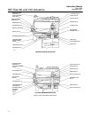
Size 80 Actuator Spring
Note
Before turning the spring adjuster on
size 80 actuators, assemble the stem
connector around the actuator stem
and the anti-rotating lug on the yoke.
Mark the actuator stem as a visual
reference to verify that stem rotation
does not occur. Remove the stem
connector before rechecking the
bench set.
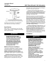
Remove the cover band (key 87, figure 6), insert a
rod of approximately 12.7 mm (1/2 inch) diameter
into a hole in the spring adjustor (key 74, figure 6),
and rotate the spring adjustor with the rod. Rotating
the adjustor from left to right will increase the loading
pressure required to start actuator stem travel;
opposite rotation will decrease the pressure required
to start travel.
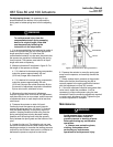
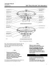
Size 100 Actuator Spring
CAUTION
The actuator must be in the vertical
position when adjusting the spring to
avoid damage to the thrust bearing
(key 86, figure 7) and to properly
position the spacers required for
adjustment.
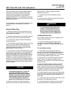
Remove the shroud plate (key 65, figure 7), and
loosen the jam nut (key 26, figure 7).
For small spring forces, adjustments can be made
by rotating the adjusting nut (key 25, figure 7).
Counterclockwise rotation (when viewed from the
diaphragm casings) of the adjusting nut will increase
the loading pressure required to start actuator stem
travel, and clockwise rotation will decrease the
pressure required to start travel. Tighten the jam nut
when adjustment is complete.