


Using the Expander Flash Utility 63
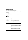
• 4 Expander A/B — Four single-RAID hosts direct connection to a 24-drive
sled
In this configuration, the four hosts are connected to the storage sled and
the 24 hard-drives are grouped into four zones. Expander chip A controls
zones 0 and 1 and expander chip B controls zones 2 and 3. See Figure 1-13.
This cabling option supports RAID cards only and allows you to manually
update the expander firmware on both expander chips one at a time. You
will need to switch the cables in the mini-SAS A1, A2 and mini-SAS B1, B2
connectors to update the second expander chip.
• 5 Expander A/B — Two single-RAID hosts direct connection to a 12-drive
sled
In this configuration, the two hosts are connected to the storage sled and
the 12 hard-drives are grouped into two zones. Expander chip A controls
zones 0 and 1. See Figure 1-15.
This cabling option supports both HBA and RAID cards and allows you to
manually update the expander firmware on both expander chips one at a
time. You will need to switch the cables in the mini-SAS A1 and
mini-SAS B1 connectors to update the second expander chip.
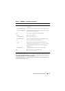
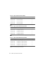
Expander Firmware File Names
The following tables show the expander firmware and manufacturing image
file name format.
Note: XXX represents the version number of the firmware image for flash region 0.
Table 4-4. Region 0 Expander Firmware File Names
Configuration Type Firmware Image File Name Region
1 Expander A/B sas2xfwZeus_XXX.fw 0
2 Expander A/B sas2xfwZeus_XXX.fw 0
3 Expander A/B sas2xfwZeus_XXX.fw 0
4 Expander A/B sas2xfwZeus_XXX.fw 0
5 Expander A/B sas2xfwZeus_XXX.fw 0