


GB
GB
1
Note: (This note applies only to engines used in the U.S.A.) Maintenance, replacement or repair of the emission control devices and systems may be performed
by any non-road engine repair establishment or individual. However, to obtain no charge repairs under the terms and provisions of the Briggs & Stratton
warranty statement, any service or emission control part repair or replacement must be performed by a factory authorized dealer.
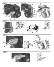
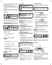
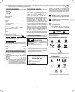
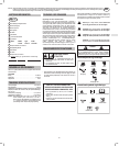
ENGINE COMPONENTS
Fig. 1
1
Rope Handle for Rewind Starter
2
Oil drain plug
3
Choke control lever
4
Throttle lever
5
Air cleaner
6
Fuel tank cap
7
Spark plug / Spark plug wire
8
Muffler
9
Engine Model Type Code
xxxxxx xxxx xx xxxxxxxx
10
Stop switch wire, if equipped
11
Oil fill cap
12
Fuel tank cap
13
Air Cleaner
14
Stop switch, if equipped
Record your engine
Model, Type and Code numbers here for
future use.
Record your date of purchase here for future use.
GENERAL INFORMATION
This is a single cylinder, L-head, air-cooled engine. It is a low
emissions engine.
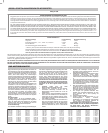
Model 90000
Bore 65.09 mm (2.56 in.). . . . . . . . . . . . . . . . . . . . . . . . .
Stroke 44.45 mm (1.75 in.). . . . . . . . . . . . . . . . . . . . . . .
Displacement 148 cc (9.02 cu. in.). . . . . . . . . . . . . . . . . .
TUNE-UP SPECIFICATIONS
Armature air gap 0.15 − 0.25 mm . . . . . . . . . . . . . . . . . .
(0.006 − 0.010 in.). . . . . . . . . . . . . . . . . . . . . . . . . . . . . .
Spark plug gap 0.76 mm (.030 in.). . . . . . . . . . . . . . . . .
Valve clearance with valve springs installed and piston 6 mm
past top dead center (check when engine is cold). See Repair
Manual P/N 270962.
Intake valve clearance 0.13 − 0.18 mm . . . . . . . . . . . . .
(0.005 − 0.007 in.). . . . . . . . . . . . . . . . . . . . . . . . . . . . . .
Exhaust valve clearance 0.18 − 0.23 mm . . . . . . . . . . . .
(0.007 − 0.009 in.). . . . . . . . . . . . . . . . . . . . . . . . . . . . . .
Note: Engine power will decrease 3-1/2% for each 1,000
feet (300 meters) above sea level and 1% for each
10_ F (5.6_ C) above 77_ F (25_ C). It will operate
satisfactorily at an angle up to 15_. Refer to the equip-
ment operator manual for safe allowable operating
limits on slopes.
TECHNICAL INFORMATION
Engine Power Rating Information
The gross power rating for individual gas engine
models is labeled in accordance with SAE (Society of
Automotive Engineers) code J1940 (Small Engine
Power & Torque Rating Procedure), and rating perfor-
mance has been obtained and corrected in accordance
with SAE J1995 (Revision 2002-05). Torque values are
derived at 3060 RPM; horsepower values are derived
at 3600 RPM. Actual gross engine power will be lower
and is affected by, among other things, ambient
operating conditions and engine-to-engine variability.
Given both the wide array of products on which engines
are placed and the variety of environmental issues
applicable to operating the equipment, the gas engine
will not develop the rated gross power when used in a
given piece of power equipment (actual on-site" or net
power). This difference is due to a variety of factors
including, but not limited to, accessories (air cleaner,
exhaust, charging, cooling, carburetor, fuel pump,
etc.), application limitations, ambient operating condi-
tions (temperature, humidity, altitude), and engine-to-
engine variability. Due to manufacturing and capacity
limitations, Briggs & Stratton may substitute an engine
of higher rated power for this Series engine.
SAFETY SPECIFICATIONS
• Read entire Operating & Maintenance Instructions
AND the instructions for the equipment this engine
powers.*
• Failure to follow instructions could result in serious
injury or death.
BEFORE OPERATING
ENGINE
* Briggs & Stratton does not necessarily know what equip-
ment this engine will power. For that reason, you should
carefully read and understand the operating instructions for
the equipment on which your engine is placed.
• Make you aware of hazards associated with
engines
• Inform you of the risk of injury associated with
those hazards, and
• Tell you how to avoid or reduce the risk of injury.
THE OPERATING &
MAINTENANCE INSTRUCTIONS
CONTAIN SAFETY
INFORMATION TO:
A signal word (DANGER, WARNING, or CAUTION) is used
with the alert symbol to indicate the likelihood and the potential
severity of injury. In addition, a hazard symbol may be used to
represent the type of hazard.
DANGER indicates a hazard which, if not avoided,
will result in death or serious injury.
WARNING indicates a hazard which, if not avoided,
could result in death or serious injury.
CAUTION indicates a hazard which, if not avoided,
might result in minor or moderate injury.
CAUTION
, when used without the alert symbol,
indicates a situation that could result in damage to
the engine.
The engine exhaust from this product contains chemicals
known to the State of California to cause cancer, birth
defects, or other reproductive harm.
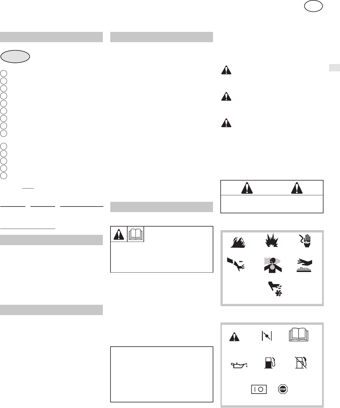
WARNING
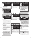
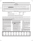
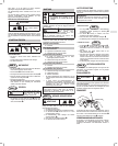
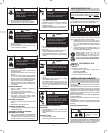
Hazard Symbols and Meanings
Explosion
Toxic Fumes
Shock
Hot SurfaceKickback
Fire
Moving Parts
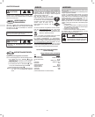
International Symbols and Meanings
Stop
Fuel Shutoff
Read Operator’s
Manual
Fuel
ChokeSafety Alert
Oil
On Off