


P. 8 Installation Guide
quenching/suppression diode, and that the Negative trigger is on the same terminal of the relay as
the Anode (+ or non-striped side) of the quenching/ suppression diode.
When a relay’s coil is energized, a magnetic field is created and energy is stored in the coil. When
power is removed from the coil, the magnetic field collapses. This causes a Reverse Voltage to be
generated and can sometimes reach 200 volts. A quenching diode absorbs this reverse voltage
spike.
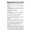
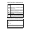
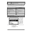
A closer look at a relay:
Now that you know what the main inscriptions are on the relay, take a look on the side, and you will
see another inscription: i.e. (12 VDV, 40/ 30 A)
12 VDC: This indicates the coil voltage rating. For an Automotive relay, it's usually 12 Volts DC.
40/ 30 A: This indicates the current carrying capability of the contacts 30, 87, & 87A.
40: Indicates that the normally closed circuit (30 and 87a) can safely handle a maximum of 40
amps of current.
30: Indicates that the normally open circuit (30 and 87) can safely handle a maximum of 30 amps
of current.
Examples: The following examples demonstrate some of the most common uses for relays:
isolation, inversion, interruption, strengthening current, and for powering multiple wires from one
source SAFELY.
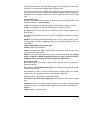
Powering multiple wires from one source safely:
Example: Powering a second Ignition
Problem: You need to power Multiple Ignition wires to remote start the vehicle, but your module
only has one Ignition output available.
Solution: You will need to add a second ignition relay to power the second ignition wire. (Jumping
Ignition 1 to Ignition 2 is NEVER recommended. Always use a relay. The vehicle circuits are
Isolated for a reason; the wiring of the remote star module should reflect this.)
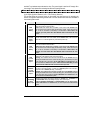
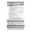
The relay connections:
85: Connects in parallel to the Ignition 1 output from the remote start module. This becomes the
positive side of the coil.
86: Connects to the Ground Out when Running wire from the remote start module. This becomes
the negative side of the coil.
87: Connected to a Fused +12 Volts source that is capable of supplying power for the vehicle's
second ignition wire. This becomes the source of power for the 2
nd
ignition wire.
87A: No connection. This terminal is not used in this application.
30: Connects to the vehicle's second ignition wire. This becomes the output of the 2
nd
ignition
relay.
Comments: The relay is only energized when the vehicle is running by remote start. When started
with the Key, the relay is not energized and the integrity of the stock system has been preserved.
Isolation:
Example: Isolating a Parking light output