


P. 14 Installation Guide
(Also known as the “wait-to-start light”.) The purpose of the Glow-plug circuit on diesel
vehicles is to pre-heat the Combustion Chamber before the vehicle is started.
When a Remote Starter is installed on a diesel vehicle, the Glow- plug section of the
Ignition circuit must be activated and allowed to operate before the vehicle is remote-
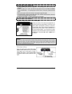
started. For that purpose, the Glow-plug input wire of the module must be connected to
the Glow-plug indicator light of the vehicle. The module will only accept positive Glow-plug
input signals, if the signal is negative, use a relay to invert its polarity. A diode must be
added between the negative Glow-plug trigger on the relay and the negative Glow-plug
wire of the car. This is to prevent feedback effects on the Glow-plug indicator light on the
instrument cluster: the light on the dash would come on because of the feedback, even
though the circuit is off.
When the user remote-starts the vehicle:
The module will power up the Ignition circuit and wait to engage the Starter Motor while
the Glow-plug indicator light is still on.
The module will engage the Starter Motor as soon as the Glow-plug light (+) goes out.
Minimum waiting time is 3 seconds.
Maximum waiting time is 30 seconds (approximately).
If no Glow-plug wire is found on the vehicle, the Glow-plug input on the module may be
“timed out”. The module will power up the Ignition and Glow-plug circuits and simply wait
for the time-out before starting.
Keeping the Glow-plug input wire of the module unconnected will hold the ignition
ON for
the preprogrammed delay.
Please program the tach before connecting the glow-plug input to the vehicle.
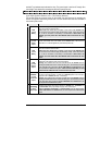
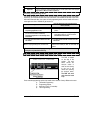
3-pin Harness
Wire Description
1
VIOLET/BLACK
(-) AUX 2 Output
500 mA negative output. Can be programmed for one of the following four options:
1. Constant while the
LOCK and UNLOCK buttons are pressed, + 1 sec. after the
buttons are released.
2. Pressing the
LOCK + UNLOCK buttons simultaneously will toggle the AUX 2 output
ON/OFF for up to 30 sec.
3. Pressing the
LOCK + UNLOCK buttons simultaneously will toggle the AUX 2 output
ON/OFF for up to 4 min. (active only when under remote run).
4. Priority door access. Produces a (-) pulse on the 2
nd
press of the UNLOCK button.
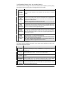
2
LIGHT BLUE
(-) AUX 1 Output
500 mA negative output. Can be programmed for one of the following three options:
1. Horn confirmation on the 2
nd
press of the LOCK button.
2. Priority door access. Produces a (-) pulse on the 2
nd
press of the UNLOCK button.
3. Horn confirmation on 1
st
press of the LOCK button.
3
WHITE/BLACK
(–) Parking lights
output
500 mA negative Parking Light output
Note: Ensure that the voltage does not vary when the dimmer control switch is turned up
or down. If this is the case, it is not the right wire.
There is also a positive Parking Light output. Only one of these two different
outputs needs to be connected.
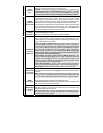
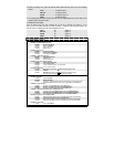
Additional Ports
Port Description
1
Temperature
Sensor
(Optional)
N/A
2
RS-232 Port
For D2D connection; is used to interface bypasses and door locks convenience module
(check bypass list for compatibility and functionalities).
3
INV-200 Port Is used to interface the pulse inverter for door locks option.
4
Bypass/GPS Port Is used for analog connection to some bypass units (check bypass list for