


Installation Guide P. 13
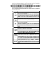
6
VIOLET
(+) Door pin
input
This input should be used in vehicles that use a positive-switching Dome Light circuit.
Connect to a Door trigger wire testing +12 V with a Door open.
CAUTION! You can only use a negative or a positive connection. In other words, only
the NEGATIVE DOOR INPUT or the POSITIVE DOOR INPUT wire is connected. It is essential
that the Module be connected in such a way as to allow each Door to turn off Ready
Mode: the driver-side Door Pin does not constitute by itself a sufficient connection.
7
ORANGE
(–) Starter Kill
(armed output)
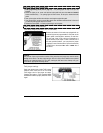
The unit is equipped with a selectable passive- or active-arming Starter Kill circuit that
will immobilize the vehicle when the system is armed. This wire will provide a constant
500-mA negative output when the system is armed (locked by remote) or if remote
started. This wire should be connected to a Single Pole Double-Throw Relay (This wire
will connect to pin 85, on the Relay, and pin 86 will be connected to the Ignition wire).
A second benefit of the Starter Kill is the Anti-Grind feature. When the vehicle has been
remote started the Anti-Grind prevents the starter motor from re-engaging when the
ignition key is inserted in the Ignition switch and accidentally turned to the
CRANK position
(The Starter Kill output becomes active during remote starts).
8
BLACK/WHITE
(–) Parking
brake Input
Connect to the negative Parking brake Indicator Light wire of the vehicle. This wire is
found at the parking brake lever itself.
Note: The wire should test ground when the Parking brake is engaged.
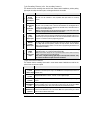
9
WHITE/BLUE
(–) External
Trigger input
The External Trigger wire can be used for remote-starting the vehicle with an external
device. When the vehicle is running, triggering this input will activate Idle Mode. The
External Trigger wire can also be used to operate as a negative trigger with the Trunk pin-
switch or the Key Sense wire (by default).
Option 1 Connects to (-) Negative Trunk pin. When this wire is programmed for trunk
pin, pressing TRUNK will activate a 1-second disarm output. If ground (-) is detected on
the trunk pin (the Trunk has been opened), an ARM pulse will be sent 5 seconds after the
Trunk is closed. An ARM pulse will be sent 4 seconds after the TRUNK button is pressed if
the Trunk pin state is unchanged (The Trunk was unopened). Disarm is sent only if the
system was previously locked and armed. If secure lock is enabled, unlock pulse(s)
will be sent with disarm, a lock pulse and a rearm pulse will be sent when the
TRUNK is closed or if the TRUNK was left closed.
Option 2 (Default: Key Sense (-) Input): Connects to OEM Key Sense Wire. When
the Key is detected in the Ignition switch (Ground (-) signal on the OEM Key Sense Wire)
the Starter Kill will not ARM even when it is set to Passive Mode. If Secure Lock is
programmed, LOCK and ARM will not be activated while the Key Sense input is active
(“active” meaning there is a key in the Ignition barrel).
Option 3 (Engine Start/Stop): The first (-) pulse on this input will start the Engine, the
second (-) pulse on this input will stop the Engine. It is also used to activate ready mode.
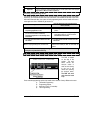
Option 4 (Pager): Enables the pager port located at the back of the remote starter.
10
BLUE/BLACK
(–) Ground out
when running
500 mA constant negative output when running.
This output becomes active before remote Ignition On, and shuts off when the module is
shut down.
Note: If multiple relays or modules are connected to the ground out wire, make sure that
each one of them is diode-isolated from the others. Otherwise feedback effects may
occur, which could damage the vehicle and/or the modules, relays, and bypass modules.
11
GREEN
(-) Door Input
This input should be used in vehicles using a negative-switching Dome Light circuit.
Connect to the Door trigger wire that tests ground with a Door open.
It should be noted that the installer should use either the positive or the negative Door
input, and never use both of them simultaneously.
12
GRAY/BLACK
(+) Glow-plug
input
This positive input will monitor the Glow Plug Light in Diesel Mode: it will wait until the
Glow Plug Light goes out to crank the Engine. Connect to the side of the Glow Plug Light
that becomes positive when the Light is on.
Note: In Diesel Mode there is an 18-sec. crank timing delay (or approximately 25-sec. if
the run time is set to 30 min.): if the Glow Plug Light is still on after the delay expires, the
module will proceed to start the Engine.