


Installation Guide P. 21
modules connected to the G.O. Wire, a relay (and diodes) may have to be added to strengthen the
negative current going to the clutch bypass.
Positive:
Very similar to the negative system, except that the vehicle's clutch relay is triggered by 12 volts
instead of a negative signal. In a Positive system, when the clutch is pressed; a positive (12 volts)
signal is sent to the relay. The relay energizes when the Key is turned to the start position The 12
volts from the start wire is allowed to pass through the relay and to the starter motor. One of the
wires at the clutch will test as 12 volts; this is the supply wire. The relay's positive trigger wire will
only show positive when the pedal is pressed (some vehicles also require the Ignition system to be
powered). A relay is needed to send 12 volts to the trigger wire from the start module during start
attempts.
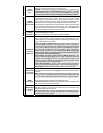
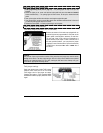
Normally Closed (N/C):
Note: There are different types of this system used by various vehicle manufacturers; the following
is used to illustrate how these systems work in general.
A Relay is also used in these types of systems to interrupt the starter wire. In the previous two
examples, the clutch was bypassed by engaging the clutch relay; with this system you bypass the
clutch by preventing the clutch relay from engaging. When the Ignition Key is turned to the start
position the relay energizes and interrupts the start wire when the pedal is not pressed. When the
Ignition key is turned to the start position and the pedal is pressed, the relay does not energize and
the start signal reaches the starter motor.
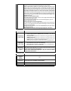
In a N/C system the supply wire is connected to the relay's trigger wire at rest (pedal not pressed).
When the pedal is pressed, the connection is broken between the supply wire and the relay's
trigger wire (this disengages the relay). To verify that you have a N/C system, disconnect the clutch
switch: the vehicle should start without the clutch pedal being pressed. When you test the trigger
wire with your DMM meter, the trigger wire will test as 12 volts or negative when the pedal is not
pressed. It should read as an open circuit (or Float) when the pedal is pressed.
Please note: Your probe may also show feedback from the other end of the circuit. The Polarity of
the Trigger wire does not matter in this system, since all you need to do in order to bypass it is to
use a relay to interrupt it during remote starts.
Installation-programmable Features
The following features can be programmed according to the needs of the installation and the
requirements of the user:
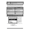
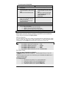
Ignition-controlled Door Locks
This feature will LOCK all doors when the brake pedal is pressed while the ignition key is in the
IGNITION ON (RUN) position. The unit will UNLOCK all doors when the ignition key is turned to the
OFF position.
• If the Ignition Lock Only Option is selected, the system will only lock the doors.
• Ignition Unlock Only is selected; the system will only unlock the doors (provided the ignition
key was in the
IGNITION ON (RUN) position and that the brake pedal was pressed at least
once).
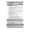
Secure Lock
This feature allows the module to control certain OEM factory alarm systems without requiring the
use of other wires for disarming the OEM alarm. (Namely, this feature is designed for OEM
systems that use the factory lock wire to arm the alarm and the unlock wire to disarm it.)