


Installation Guide P. 11
module's Trunk release output activates the relay. The ground signal is sent from 87 through 30 to
the vehicle's Trunk release wire activating the switch and opening the trunk.
Harness Description
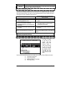
6-pin Main Ignition Harness (a.k.a. The Primary harness)
The two Red wires are the power inputs for the module; the other wires are for recreating the
actions of the Ignition switch during remote starts. On most vehicles these wires are connected at
the vehicle's Ignition switch.
Wire Description
1
RED
(+) 12 V
Battery
Connect to the largest 12 V supply wire at the Ignition harness. Ensure that the OEM
power wire is fused for more than 30 A.
NOTE: Certain new vehicles have no suitable 12 volts source at the IGNITION switch
(the 12 Volt wire is too small to supply the necessary current). In this case, the fuse
box, or the B+ connection on the battery is recommended. If wires need to be
extended, you must protect them with additional fuses connected at the entry
source.
2
VIOLET
(+) 30 A
starter
output
Connect to the Starter wire of the vehicle (at the
IGNITION switch). The source wire
should have +12 V with the Ignition Key in the Crank position only.
3
RED
(+) 12 V
Battery
Connect to the largest 12 V supply wire at the Ignition harness. Ensure that the OEM
power wire is fused for more than 30 A.
NOTE: certain new vehicles have no suitable 12 volts source at the IGNITION switch
(the 12 Volt wire is too small to supply the necessary current). In this case, the fuse
box, or the B+ connection on the battery is recommended. If wires need to be
extended, you must protect them with additional fuses connected at the entry
source.
4
PINK
(+) 30 A
ignition
output
Connect to Ignition wire of the vehicle. The source wire should have +12 V with the
Ignition Key in the Ignition On (Run) and Crank positions.
Warning: some vehicles have more than one IGN wire at the IGNITION switch for
powering the heater blower motor. Use the 5th relay (pin F) and extra relays to power
up any extra IGN. wires if necessary. DO NOT JUMP WIRES at the IGNITION switch, this
will compromise the OEM electrical system. If wires need to be extended, you must
protect them with additional fuses connected at the entry source.
5
ORANGE
(+) 30 A
Accessories
output
This wire is for powering the heater blower motor. It is usually classified as an Acc.
(no power in the crank position.) if it tests as an
IGNITION (power in the crank pos.)
then power it as an
IGNITION (5th relay, or extra relay).
Warning: some vehicles have more than one ACC wire at the IGNITION switch for
powering the heater blower motor. Use the 5th relay (pin F) and extra relays to power
up any extra ACC. wires if necessary. DO NOT JUMP WIRES at the IGNITION switch, this
will compromise the OEM electrical system.
6
PINK/WHITE
(+) 30 A 5
th
relay output
This high-current output can be used to power a
2
nd
IGNITION or a 2
nd
ACCESSORY or a
2
ND
STARTER WIRE. See jumper settings on page 19 for correct output.
Additional IGNITIONS, ACCESSORIES, or STARTER WIRES must use external relays.
DO NOT JUMP WIRES at the IGNITION switch, this will compromise the OEM electrical
system.