


P. 12 Installation Guide
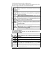
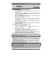
5-pin Secondary Harness (a.k.a. the secondary harness)
This harness has the remaining wires used in basic remote starter installations, positive parking
light output, the safety shut down inputs, and the ground wire for the module.
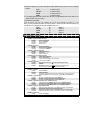
Wire Description
1
BLACK
(–) Chassis
ground input
This wire must be connected to bare, unpainted metal (the Chassis or true Body
ground).
2
VIOLET/WHITE
(AC)
Tachometer
input
This wire tells the module if the Engine is running or not. It requires at least 1.8 volts
(AC) and 1.5 Hz (or faster) at idle. Common Tach references are: the negative side of
an injector, the negative side of an Ignition Coil, Camshaft sensor, Crankshaft sensor or
the Engine Control Module (ECM).
NOTE: A Tach signal that is too low will cause the module to “over crank” and a Tach
signal that is too high will cause the module to “under crank”.
3
GRAY
(-) Hood
switch input
For safety reasons, this wire must be connected to the hood pin provided in the box or to
the OE hood pin. This input will disable or shut down the Remote Starter when the hood
is opened. It can also be used for programming purposes.
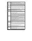
4
BROWN
(+) brake
switch input
This wire must be connected to the brake Light switch of the vehicle. The wire should be
+12 V only while the brake pedal is pressed. This input will shut down the Remote
Starter if the brake pedal is pressed. It is also used for programming and therefore it is
essential that it is installed.
5
WHITE
(+) 12 V
Parking Light
output
This wire provides a +12 V output (15 A max.) and must be connected to the Parking
Light wire that tests +12 V when the Parking lights are
ON.
Note: Ensure that the voltage does not vary when the dimmer control switch is turned up
or down. If this is the case, it is not the right wire.
There is also a negative Parking Light output on the 3-pin side connector. Only
one of these two different outputs needs to be connected.
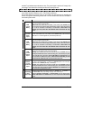
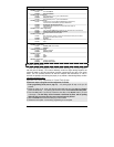
12-pin Accessories Harness
This harness has the remaining wires used in some remote starter installations as well as the
optional user convenience outputs.
Wire Description
1
RED/WHITE
(–) Trunk
or AUX 3 output
500 mA negative output. This can be used to control trunk release (1-sec. pulse) or to
operate as a constant output as long as the TRUNK button is held pressed (for Sunroof or
Window close).
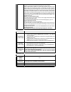
2
LIGHT GREEN
(–) Lock
Programmable 500 mA 1/10-sec., 7/10-sec. or 4-sec. negative output.
3
BLUE
(–) Unlock
Programmable 500mA 1/10-sec., 7/10-sec., 4-sec. or 1/4-sec. double-pulse negative
output.
4
LIGHT
GREEN/WHITE
(–) Arm
Max 500 mA negative output when the doors are locked by remote control. This wire will
provide a negative output 1/4 sec. before the lock pulse, and go off 1/8 sec after it. Note:
The system will also give a rearm pulse on this wire after remote-start shutdown.
5
LIGHT
GREEN/BLACK
(–) Disarm
Max 500 mA 1-sec. negative pulse when the Doors are unlocked by remote control.
Connect to the OEM Disarm wire of the vehicle. Note: The system will also give a disarm
pulse on this wire before remote starts.