


P. 20 Installation Guide
Clutch Bypass
In order to remote start a manual transmission vehicle, the clutch switch must be bypassed. Clutch
safety switch circuits can take many forms. Listed below are the most common ones. Some
vehicles may also have a separate or combined switch on the clutch pedal for cruise control.
Usually a cruise control switch reacts the moment you touch the pedal, whereas a clutch switch
reacts only when the pedal is near the floor. Once the circuit type has been determined, you must
recreate what happens electrically at the switch, with the remote start module, to bypass the clutch
during remote starts. Relays are often used to accomplish this. Always use the Ground Out When
Running (G.O.) as the negative trigger on your clutch bypass relays, as it is only active during
remote starts. NEVER permanently bypass a clutch switch. Do not attempt this if you are unfamiliar
with the use of relays and diode isolation.
Before any wiring attempts, test and record the way each wire tests in the following
positions:
Without the pedal pressed:
♦ test the wire with the Ignition OFF
♦ test the wire with the Ignition ON
♦ test the wire with the Key in the start position
With the pedal pressed:
♦ test the wire with the Ignition OFF
♦ test the wire with the Ignition ON
♦ test the wire with the Key in the start position
With this information for every wire at the switch, determining what type of clutch switching system
you have will be easy.
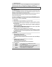
Direct Feed:
The simplest type of system to test and bypass is the “Direct Feed” system. This circuit simply
interrupts the +12v signal starter wire from the ignition switch to the starter solenoid. There are 2
wires in this circuit, the “key side” wire which goes from the clutch pedal to the Ignition switch, and
the “solenoid side” which goes from the clutch switch to the starter motor. When the key is turned
to the start position without pressing the pedal, you will test 12v only on one of the wires at the
clutch switch; this is the key side. When the pedal is pressed down and the key is in the crank
position, the other wire will also read 12 volts; this is the solenoid side wire. Connect the starter
output from the remote starter to solenoid side wire.
Note: In the next two systems a Relay in the vehicle interrupts the start wire between the Ignition
switch and the starter motor. With the key in the start position and the clutch pedal pressed, the
relay energizes and allows the start signal to reach the starter motor. In these systems a wires from
the clutch triggers the relay when the pedal is pressed. There will be another wire at the clutch
switch that supplies the signal to the trigger wire (either positive or negative, depending on the
system).
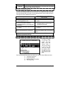
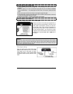
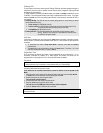
Negative:
In a Negative system, when the clutch is pressed, a negative signal is sent to the relay. The relay
energizes when the Key is turned to the start position. The 12volts from the start wire is allowed to
pass through the relay and to the starter motor. One of the wires at the clutch will test as negative;
this is the supply wire. The relay's negative trigger wire will only show negative when the pedal is
pressed (some vehicles also require the Ignition system to be powered). If there is nothing else
connected to the Ground Out When Running (G.O.) wire from the remote start module, the G.O.
wire should be strong enough to trigger the vehicle's clutch relay. If there are other devices or