Chapter 3 Visual User Interface
Receiver Status Screen Data
3-12 Operating and Programming Guide
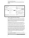
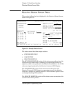
SYNCHRONIZATION Section of the Status Screen
SYNCHRONIZATION Summary Line
The SYNCHRONIZATION line in the screen summarizes the
SmartClock Status and Reference Outputs. One of three
SYNCHRONIZATION messages is shown:
Outputs Invalid while the Receiver (unit) is warming up,
Outputs Valid/
Reduced Accuracy while the unit is in holdover or is locked but has
not achieved steady-state operation, or
Outputs Valid while the unit is in steady-state operation.
SmartClock Mode
The SmartClock Mode area of the screen shows the four operating
modes:
•Locked to GPS
• Recovery
•Holdover
• Power-up
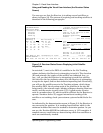
As shown in the sample status screen in Figure 3-6, a >> symbol
indicates the current operating mode.
Locked to GPS indicates that the Receiver is locked to GPS. The
front-panel GPS Lock LED will be illuminated.
When stabilizing frequency ... is shown, the time output (1 PPS) signal is
locked and can be used, but the frequency outputs (10 MHz) are not at
their final or most stable state.
Recovery indicates that the Receiver is actively working to become
locked to GPS. All conditions needed to proceed towards a lock have
been met. Expect an eventual spontaneous transition to a lock (unless
changing external conditions prevent this, such as loss of tracked
satellites.)
Holdover indicates that the Receiver is waiting for conditions that are
needed to allow the process of recovery from holdover to begin. Once
these conditions are met, the Receiver will transition on its own to the
recovery mode.
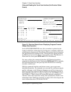
When the GPS 1PPS CLK invalid message follows the Holdover label,
the internal GPS 1 PPS reference signal is inaccurate.


