


Chapter 1 Front and Rear Panels at a Glance
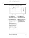
59551A Rear Panel at a Glance
1-6 Operating and Programming Guide
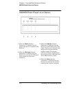
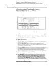
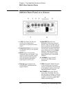
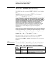
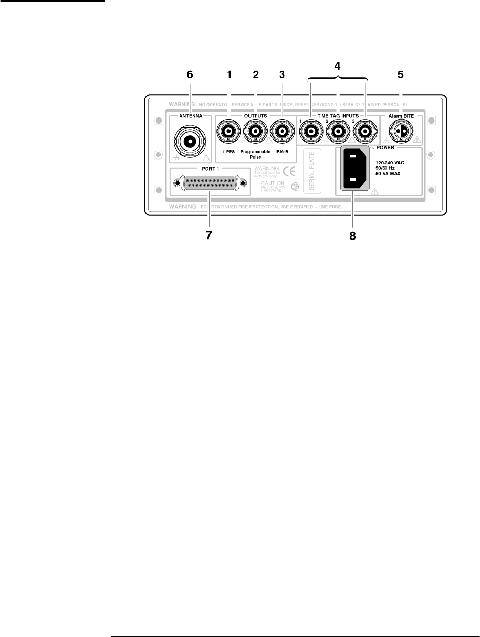
59551A Rear Panel at a Glance
1 1PPS (One-Pulse-Per-Second)
connector for outputting a
continuous one pulse per second
signal.
2 Programmable Pulse output connector
for outputting pulses at user-specified
time/period.
3 IRIG-B output for outputting
formatted time-code signals. (This
signal is used for general purpose
time distribution and magnetic
tape annotation applications
requiring the time of year.)
5 Alarm BITE (Built-In Test
Equipment) output for external
devices (such as red light, bell, or
horn) to indicate that the Module
has detected an internal condition
that requires attention. The relay
opens and closes with the Alarm
indicator. (Mating connector is
Amphenol part number 31-224
[glass-filled Noryl] or #31-2226
[Telfon]).
6 ANTENNA N-type (female)
connector for GPS antenna
connection.
4 Time tag input connectors for
receiving TTL conditioned time
tagging signals.
7 PORT 1 RS-232C, DB-25 (female)
serial interface port for remote
control, monitoring, and retrieving
of the Module’s memory data and
upgrading Module software.
8 AC POWER input jack. The AC
input jack is standard. The unit
operates from ac voltage. It can also
be operated from dc voltage via this
ac jack by using the supplied IEC
320 dc connector plug.