Series 820 Instruction Manual Chapter 4 Maintenance & Repair
IM-82-C 4-11
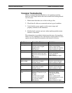
Transducer Troubleshooting
When you suspect that the transducer is not operating correctly,
there are a few simple checks that can be made before taking the unit
out of service:
1. Make certain that there are no leaks in the gas line.
2. Check that all cables are connected and are in good condition.
3. Verify that the power supply is in the correct range and
properly connected to the transducer.
4. Double check connector pin outs when replacing another manu-
facturer’s transducer.
This information is provided to help locate the cause of a transducer
failure. It is not intended to be an all inclusive repair guide. For most
repairs, the unit should be returned to the factory for service.
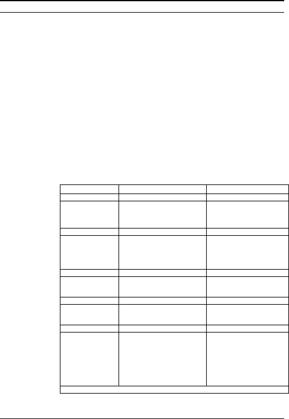
Problem Possible Cause Solution
No output No power
Inlet filter screen clogged
Clogged sensor
PCB defective
Plug in power supply
Clean or replace screen
Return to factory for cleaning*
Return to factory for repair
Unit will not zero Gas leak
Application requires high pres-
sure and non-horizontal mount-
ing
PCB defective
Find and correct leaks
Re-zero transducer
(see Chapter 3)
Return to factory for repair
Reads full scale
with no flow
Gas leak
Liquid present in system
Defective sensor
Find and correct leaks
Check for liquid in flow path
Return to factory for repair
Output too high Incorrect calibration or K-factor
Liquid present in system
Defective sensor
Correct calibration/k-factor
Check for liquid in flow path
Return to factory for repair
Out of calibra-
tion
Dirty or clogged sensor
Change in composition of gas
Gas leak
LFE dirty
Inlet filter screen clogged
Incorrect inlet conditions
(1/2-inch size models)
PCB defective
Return to factory for cleaning*
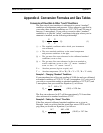
See K-factory tables
Find and correct leaks
Clean LFE
Clean or replace screen
Re-plumb transducer correctly
(See Chapter 2)
Return to factory for repair
*Model 822-S/824-S see sensor cleaning instructions


