


Chapter 2 Installation Series 820 Instruction Manual
2-4 IM-82-C
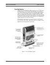
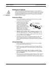
Wiring the Transducer
Standard Top-Trak
™
transducers require a 12 to 18 VDC power
supply (15 VDC nominal, 100 mA maximum). 24 VDC input power
is optional. Transducers are connected to the power supply through
either the dedicated DC power jack or through the 9-pin D-connector
located on the side of the enclosure. Before powering the unit, check
the transducer’s nameplate to confirm input power:
• PV1 = 12 to 18 VDC
• PV2 = 24 VDC
Note: operating a 24 VDC transducer at 12 to 18 VDC will result in
unreliable operation.
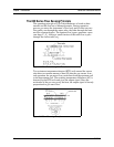
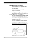
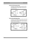
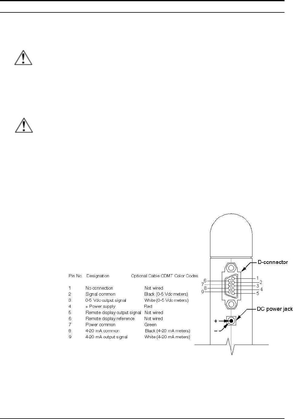
The transducer’s standard 0 to 5 VDC (4-20 mA optional) output
signal is available through the D-connector. The mating connector is
included with the transducer. Connection details are given on the
following pages.
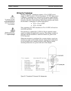
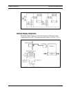
When the transducer is configured for a remote display, signal con-
nections are made via the 9-pin connector. Input power connections
are not included in the standard interface cable. Remote display
mounting dimensions are given at the end of this chapter.
Figure 2-2. Transducer D-Connector Pin Assignments
Caution!
Do not supply +DC power
at the D-connector while
using a power supply at the
power jack. Both supplies
may be damaged.
Caution!
Operating a 12 VDC trans-
ducer at 24 VDC will cause
equipment damage.