


Chapter 2 Installation Series 820 Instruction Manual
2-2 IM-82-C
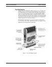
Installing the Transducer
Follow the installation instructions that apply to your transducer’s
process connection. For all 1/2-inch size process connections, observe
the piping recommendations given on page 2-3. Before operation, all
plumbing should be checked carefully for leaks and the transducer
purged with dry nitrogen.
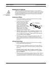
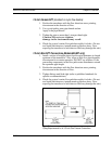
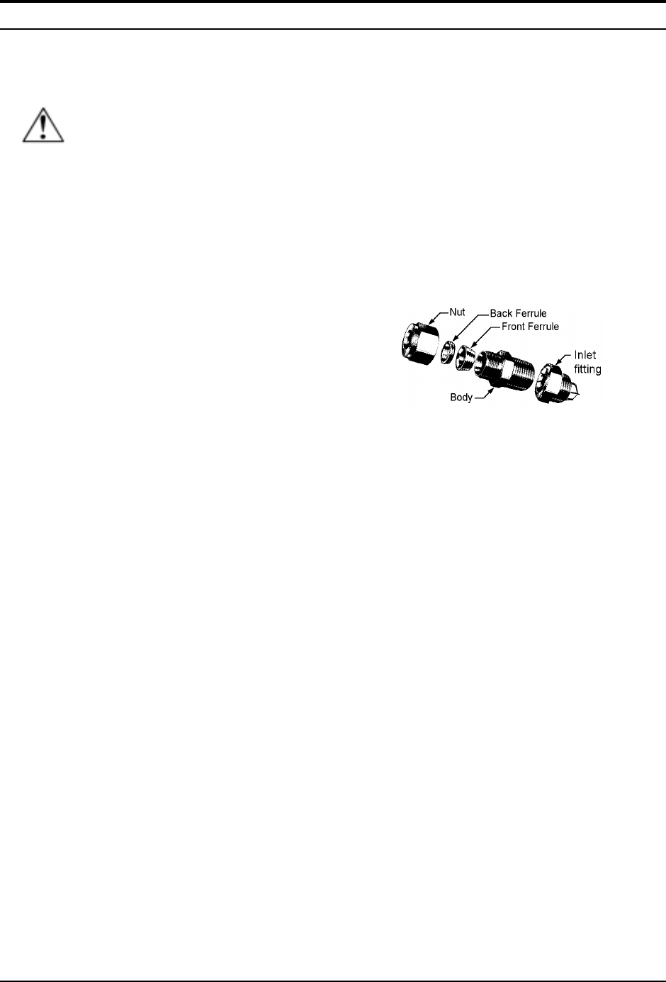
Compression Fittings
1. Position the transducer with the flow direction arrow pointing
downstream in the direction of flow.
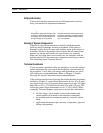
1. Verify the position of the front
and back ferrule. Insert the
tubing into the fitting. Make
sure that the tubing rests
firmly on the shoulder of the
fitting and that the nut is finger
tight. (Do not mix or inter-
change parts of tube fittings
made by different manufacturers.)
2. Hold the body steady with a backup wrench. For 1/2-
inch size, tighten the nut 1-1/4 turns from finger tight. For 1/8-
inch, 1/4-inch and 3⁄8-inch sizes, tighten only 3/4 turn from fin-
ger tight. Do not over-tighten!
3. Check the system’s entire flow path thoroughly for leaks. (Do
not use liquid leak detectors, instead monitor pressure decay.
Over-exposing the transducer to leak detector fluid may damage
the unit.)
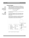
VCO and VCR Fittings
1. Position the transducer with the flow direction arrow pointing
downstream in the direction of flow.
2. Install new o-rings compatible with the gas to be used. (Do not
mix or interchange parts of tube fittings made by different manu-
facturers.)
3. Hold the body steady with a backup wrench. Tighten
the nut finger tight and then 1/4 turn tighter with a wrench. Do
not over-tighten!
4. Check the system’s entire flow path thoroughly for leaks. (Do not
use liquid leak detectors, instead monitor pressure decay. Over-
exposing the transducer to leak detector fluid may damage the unit.)
Caution!
Only qualified
personnel should install
the transducer.