


Series 820 Instruction Manual Chapter 3 Operation
IM-82-C 3-1
Chapter 3 Operation
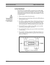
The output signal of the transducer is either 0-5 VDC (standard) or
4-20 mA (optional). The output signal is linear and proportional to
the gas mass flow rate. For example, for a 0-5 VDC output signal,
5.00 VDC is the output signal for the full scale listed on the trans-
ducer’s nameplate, 2.50 VDC is for one-half of full scale, and 0.00
VDC is for zero flow. For a 4-20 mA output signal, 20.00 mA is the
output signal for the full scale, 12.00 mA is for one-half of full
scale, and 4.00 mA is for zero flow.
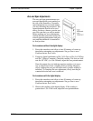
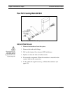
Transducer Operation
When the transducer is installed and the system has undergone a
complete leak check:
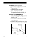
1. Apply power. The output signal will be at a high level for the
first 10 to 20 seconds while the sensor warms up to its normal
operating temperature range. Assuming zero flow, the output
signal will then drop to zero (or 4 mA, depending on output con-
figuration). Allow at least thirty minutes of warm-up time.
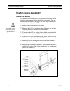
2. For first-time start ups, perform an initial zero output check as
described on page 3-3. After checking the initial zero setting, the
transducer is ready to monitor the gas mass flow rate.
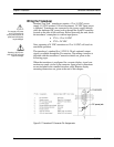
Transducer Accuracy
The standard accuracy of Top-Trak is ±1.5% of full scale. The
±1.5% of full scale accuracy means that the 0-5 VDC output signal
is accurate to within ±0.1 VDC. The 4-20 mA output is accurate to
within ±0.4 mA.
For example, the output signal for zero flow can be as much as
+0.1 VDC or +0.4 mA. If the transducer has an output signal at
zero flow, as long as it is within either of these two ranges, it does
not mean it is malfunctioning.
For transducers with a digital display, the accuracy is simply 1.5
times the full scale flow rate stated on the nameplate. For example,
if the full scale is 10 slpm, the digital display will be accurate to
±0.2 slpm. The reading at zero flow may be as much as +0.2 slpm
and still be within the stated accuracy specification.