Series 820 Instruction Manual Chapter 4 Maintenance & Repair
IM-82-C 4-7
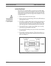
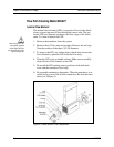
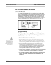
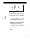
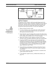
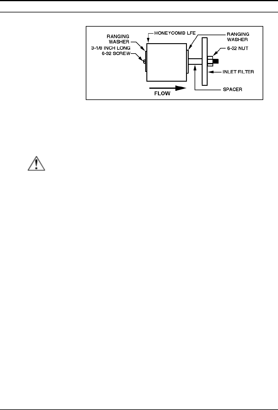
Figure 4-6. High Flow Transducer LFE Cleaning
High Flow Transducers:
The high flow LFE is similar to the honeycomb element used in the
medium flow body but larger in diameter. The high flow body consists
of four parts: inlet tube, inlet cap, main flow body and end cap. The
inlet tube is only removed to inspect and replace the sealing O-ring
between the inlet tube and inlet cap. To access the components:
1. Remove the unit from the system.
2. To remove the inlet screen, remove the four 1⁄4-28 socket head
cap screws on the inlet side of the flow body and separate the
inlet cap from the main flow body.
3. Inspect the inlet screen for damage and corrosion and replace if nec-
essary. Light to medium particulate contamination can be cleaned by
back washing with a suitable solvent. Air dry thoroughly.
4. Inspect the sealing O-ring for damage and replace if necessary.
The inlet screen is mounted with the fine mesh side facing the inlet.
5. To remove the LFE loosen and remove the four threaded rods
holding the end cap to the main flow body. Separate the end cap
from the main flow body and remove the LFE assembly. The LFE
assembly consists of: 6-32 x 31⁄8 inch long screw, a #6 washer,
two ranging washers, honeycomb laminar flow element, LFE,
spacer, inlet filter, and 6-32 nut.
6. Inspect the honeycomb element for damage and replace if neces-
sary. Replacement of the LFE or inlet screen requires transducer
re-calibration.
7. Re-assemble components. When the transducer is installed in the
system, leak test the connection.
8. To be within the original accuracy, calibrate the transducer (see
page 4-9).
Caution!
When using toxic or cor-
rosive gases, purge the
unit thoroughly with inert
dry gas before disconnect-
ing from the gas line.


