


Series 820 Instruction Manual Chapter 2 Installation
IM-82-C 2-1
Chapter 2 Installation
Installation Overview
To ensure a successful installation, inlet and outlet tubing should be
clean and free from burrs or rims caused by cutting prior to plumb-
ing the transducer into the system. The protective caps covering the
inlet/outlet fittings should not be removed until immediately prior to
installation.
Before installing the transducer, verify the following:
1. Make sure the installation site meets the specific operating pa-
rameters recorded on the transducer’s nameplate. Each trans-
ducer is factory-configured for a specific gas and flow range. If
the operating pressure is more than 50 psi (3.4 bar) away from
the calibration pressure, it is advisable to return the unit to the
factory for re-calibration. (Adjusting zero may be sufficient to
remain within specification.)
2. Do not locate the transducer in areas subject to sudden tempera-
ture changes, moisture, drafts or near equipment radiating sig-
nificant amounts of heat. Make sure to allow adequate space for
cable connectors and wiring.
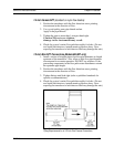
3. For 1/2-inch size inlet/outlet process connections on models 826
and 827 make sure the location meets the minimum number of
recommended pipe diameters upstream and downstream of the
transducer. A minimum of 5 inches (127 mm) upstream and 2-
1/2 inches (64 mm) downstream is always recommended. (not
necessary for other models)
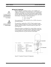
4. Horizontal mounting is preferable. Vertical mounting is possible
with best results achieved when the factory calibration is specifi-
cally performed for vertical mounting. In vertical positions zero
shift will occur depending on the gas pressure at zero flow.
5. If the gas contains any particulate matter, install an in-line filter
prior to the transducer. Recommended filter size: 15 micron for
flows of 10 sccm to 30 slpm, 30 micron for above 30 slpm.
6. If a potential over-flow condition exists, insert a valve or critical
orifice in the line to limit flow to approximately 25 percent above
the full scale range of the meter.
7. Confirm that the transducer o-ring material is compatible with
the gas to be measured.
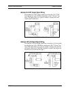
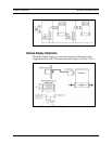
8. For remote displays, confirm the supplied cable is of sufficient
length to connect the components.