


Chapter 4 Maintenance & Repair Series 820 Instruction Manual
4-6 IM-82-C
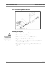
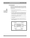
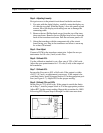
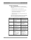
Figure 4-5. Medium Flow Transducer LFE Cleaning
Medium Flow Transducers:
In the medium flow body, the LFE assembly consists of the honey-
comb laminar flow element, inlet screen, 0.63 inch long standoff,
two ranging washers, 2-1⁄4 inch long 4-40 screw and 4-40 nut.
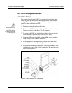
Range changes in the honeycomb element are made with various di-
ameter ranging washers. To access the components:
1. Remove the unit from the system.
2. Access the LFE by unscrewing the four 10-32 socket head cap
screws from the inlet side of the flow body and remove the inlet
end cap. (Note the position of the screws, one has a shorter
length.)
3. Remove the LFE assembly taking care not to bend the inlet
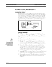
screen. Inspect the sealing O-ring and replace if necessary. In-
spect the inlet screen and replace if corroded or damaged. Light
to medium particulate contamination can be cleaned by back
washing with a suitable solvent. Air dry thoroughly.
4. Inspect the honeycomb element for damage and replace if neces-
sary. Replacement of the LFE or inlet screen requires transducer
re-calibration.
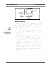
5. Re-assemble components. When the transducer is installed in the
system, leak test the connection.
6. To be within the original accuracy, calibrate the transducer (see
page 4-9).
Caution!
When using toxic or cor-
rosive gases, purge the
unit thoroughly with inert
dry gas before disconnect-
ing from the gas line.