


44 ST4000+ Wheel & Tiller Autopilots: Owner’s Handbook
5 Installing the ST4000+
5.1 Planning the installation
Before you start installing the autopilot system, read through the
relevant installation sections in this chapter.
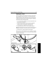
After reading through the following EMC installation guidelines,
identify suitable locations for each part of the system:
• consider how you will run cables to and from each component
• avoid running cables through bilges where possible
• avoid running cables close to fluorescent lights, engines, radio
transmitting equipment etc.
Tools required
To install this autopilot system you will need the following items:
• tape measure (metric/imperial)
• pliers and cross-head/pozi-drive screwdriver
• drill and drill bits:
• 5 mm (
5
/
32
in) for surface mount control unit
• 3 mm (
1
/
8
in) for compass and rudder position sensor
• pencil, masking tape and center punch
• sandpaper/file to smooth cut edges
• for the control unit:
• jigsaw or 90 mm hole cutter (for the control unit aperture)
• SeaTalk cables (if required – see page 52)
• extra power cable (if required - see page 52)
• for the tiller drive only:
• two-part epoxy adhesive for tiller pin and mounting socket
• installation accessories (if required – see page 61)
• drill bits as required
• appropriate power cable (see page 68) for the tiller socket
• for the wheel drive only:
• spanner for the wheel nut
• washing-up liquid (to lubricate the spokes)
• hacksaw to cut the pedestal bracket
• 4 mm + 6 mm drill bits and 3 mm allen key (supplied)
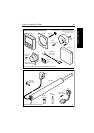
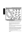
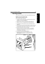
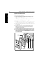
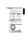
Parts supplied
Use the following illustrations to check the parts supplied with your
ST4000+ autopilot system.