


21
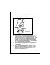
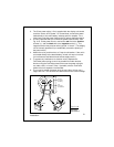
2. The 5-foot power cable (1.5 m) supplied with the display unit should
reach the source of DC power. On a small boat, connect the power
leads directly to the main battery isolation switch or breaker. On a
larger boat, route the power leads to the DC power distribution panel.
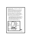
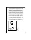
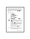
3. It is very important that you connect the power leads correctly. See
Fig. 2-16. At the power source, connect the
red
wire to the
positive
terminal (+), and the
black
wire to the
negative
terminal (-). The
negative terminal may also be called “ground” or “earth.” (The display
unit is internally protected if you accidentally reverse the polarity of
the power wires.)
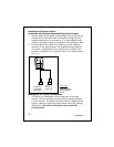
4. Attach the red or positive wire to a 5 amp circuit breaker. If the unit is
connected directly to the boat’s battery, include a 2 amp in-line fuse.
(In-line fuses are available at most marine supply stores.)
5. To prevent any interference or electrical noise, separate the
FishFinder power wiring as much as possible from other devices.
Avoid running the FishFinder power wires near the power wiring for
any radar, radio, or Loran-C units. If possible, wire the FishFinder
power wires to a separate circuit breaker.
6. If you need to extend the power wiring by more than 10 feet, use a
larger wire size. This will allow the wires to deliver the correct voltage
Fig. 2-16
DC Power
Connections
Installation
T/D
connector
to transducer
DC 12V
connector
to battery
BLACK
RED
DC 12V