


17
Installation
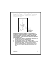
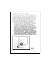
4. Drill the two small holes for the threaded studs as shown on the
mounting template. Use a 7/32" (5.5 mm) drill bit.
5. Remove the template and draw straight lines between the 1/2" holes.
Cut along each of the lines with a small saw.
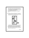
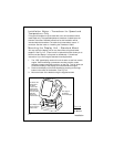
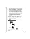
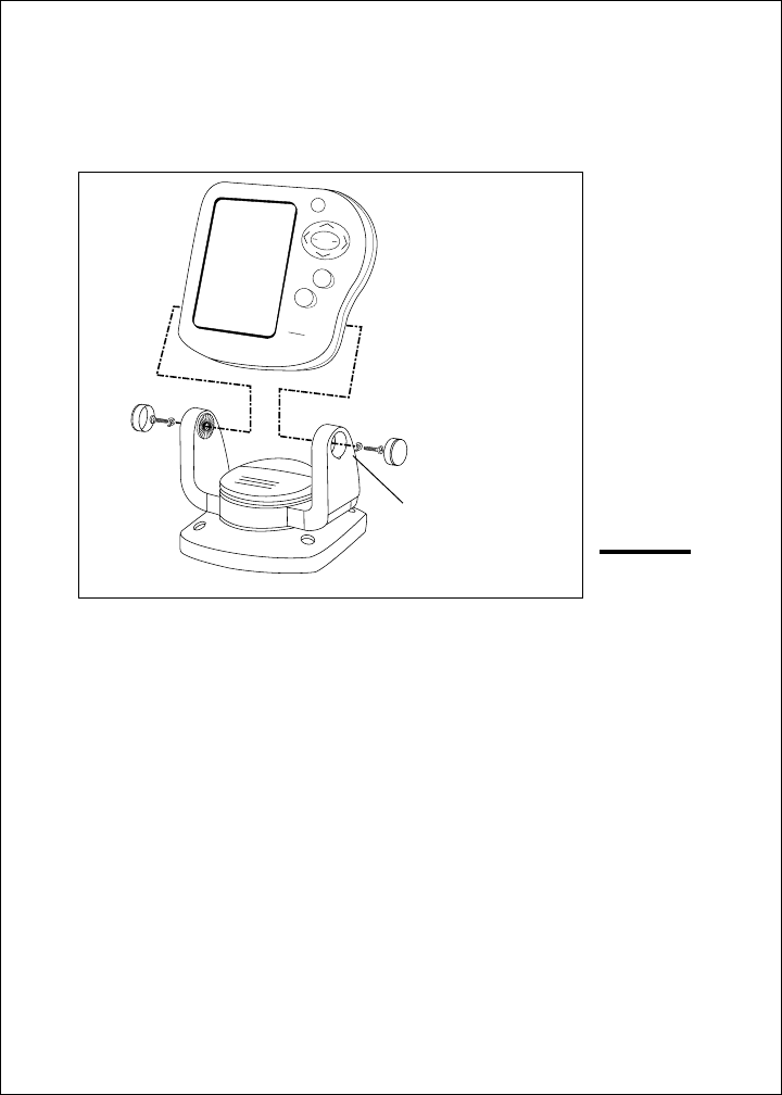
6. Separate the display unit from the mounting bracket. (See Fig. 2-12.)
Press the large button in the center of the bracket to separate the
bracket arms. The display unit is attached to the arms by two screws.
Each screw is covered by a cap. Locate the small slot beside each
cap and pry upward using a small screwdriver. Remove the caps,
then the two screws and the two wave washers. Save these parts in
case you ever want to use the mounting bracket.
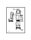
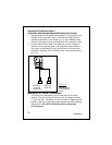
7. Screw the threaded studs into the holes on the rear of the display unit.
8. Set the display unit into place to be sure that it will fit correctly.
Thread the wing-nuts onto the threaded studs to hold the display unit
in place temporarily.
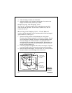
9. Once the DC wiring is complete, finish the installation. Hold the
gasket in place around the opening. Fit the display into the cutout
again. From the rear, screw the thumbscrews securely onto the
threaded studs to hold the unit in place.
To pry up the cap
insert a small screw-
driver here
Fig. 2-12
Disassembling
from Bracket
PWR
SETUP
PAGE
CLEAR
FISHFINDER
L365
Raymarine