


ACT2000
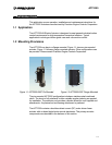
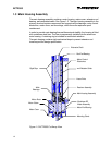
1.4 Brushless DC Motor Assembly
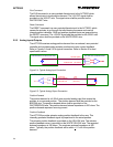
A brushless DC motor powers the ACT2000 linear drive mechanism. The DC
motor contains a stator and rotor. See Figure 1-3
Motor Stator
The motor stator is attached to the main housing by a pre-loaded wave spring
and screws. Thermistors are embedded in the stator windings to monitor winding
temperatures. The motor electrical power and thermistor wires pass from the
motor through a conduit into the electronics housing.
Motor Rotor
The motor rotor is locked to the ball screw shaft via a straight key. The motor rotor
contains powerful magnets that align with the energized stator windings thereby
creating torque and shaft rotation.
1.5 Motor Control Electronics
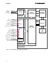
The motor control electronics (MCE) are contained within the main housing
electronics enclosure. The MCE includes harnesses, heat sink, digital and driver
component assemblies (CA).
The MCE electronics communicate with the user’s controller through analog and
serial interfaces. The MCE controls the brushless DC motor, to position the
actuator based on position feedback from the resolver.
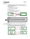
Note: The digital board analog and discrete interfaces are electrically
isolated. The MCE serial interface is NOT electrically isolated.
1.6 Resolver Assembly
A Brushless, non-contacting resolver is the primary ACT2000 feedback sensor.
A sinusoidal feedback signal is provided from the resolver to the motor control
electronics. A sinusoidal signal from the MCE provides the resolver excitation.
The resolver includes a stator and rotor. See Figure 1-3
Resolver Stator
The resolver stator is clamped to the main housing between the main bearing
retaining nut and resolver retainer. The resolver stator angular position relative to
the rotor is adjustable. Electrical wires from the resolver are reeled in the resolver
adapter to allow rotation. The resolver wires, along with the motor and thermistor
leads, are routed through a conduit into the electronics housing.
Resolver Rotor
The resolver rotor is mounted by a key to a ball screw shaft. As the rotor rotates,
the stator transformer output signal provides shaft rotation information to the
MCE.
1-3