


ACT2000
Note: The clevis can be rotated to any orientation to support installation.
To rotate, loosen the four retaining screws and rotate to desired
angle. Screw pattern can be indexed ± 45 degrees to provide
additional adjustment. Torque the four retaining screws to
117-138 in-lbs.
WARNING:
Explosion Hazard – Do not remove the clevis. Removing the clevis violates
the warranty.
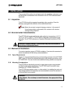
The extension rod has a 0.375-24 UNF-3B female thread for user-provided
hardware. The user may provide a standard 0.375-24-3B rod end
(recommended) or other appropriate mounting hardware. The extension rod has
wrench flats to counteract mounting hardware installation torque.
WARNING:
Property Damage Hazard – Always use the extension rod wrench flats
when installing mounting hardware. Failure to use the wrench flats may
damage or break the internal anti-rotation guide.
3.3.3 Extension Rod Movement
With 120 VDC power removed, the ACT2000 extension rod is free to move.
Approximately 60 to 100 lbf is required to extend or retract the extension rod. A
rod guide is provided internally to prevent extension rod rotation.
WARNING:
Property Damage Hazard – Do not attempt to rotate the extension rod. This
may damage the internal anti-rotation guide and void the warranty.
3.4 Electrical Installation
The ACT2000 is suitable for use in hazardous locations. See nameplate
for certifications. Care should be taken to ensure compliance with the factory
recommendations. Wiring must be in accordance will local authorities jurisdiction.
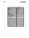
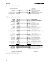
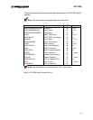
3.4.1 Wiring Specifications and Requirements
This section describes the recommended power and control harness wiring to the
ACT2000. Please consult the factory if there are any questions. See Table 3-5 for
DC power supply requirements.
3-4