


ACT2000
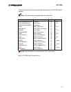
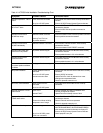
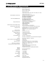
Table 4-1 ACT2000 Initial Installation Troubleshooting Chart
Symptom Probable Causes Corrective Action
Actuator Inoperative - FAULT
alarm
Power Wires not connected
No or low 120 VDC power
Ensure RED and GREEN wires correctly connected to
Actuator
Ensure 120 VDC Primary System Power at Actuator
Actuator Inoperative -
NO FAULT alarm
No RUN or position command Ensure VIOLET and WHITE/VIOLET wires correctly
connected to Actuator
Ensure 24 VDC RUN and position command at
Actuator
Actuator moves toward
HOME then stops
Intermittent RUN command
Homing Force Too Low
No position demand
Ensure consistent 24 VDC RUN and position command
Ensure position command at actuator
Actuator moves toward
HOME intermittently
Intermittent RESET command Ensure GRAY and WHITE/GRAY wires correctly
connected to Actuator
Ensure consistent 24 VDC RESET command
Actuator finds HOME then
moves to STOP position
No position demand signal Ensure BROWN and WHITE/BROWN wires correctly
connected to Actuator
Ensure position demand > 2.0 mA at Actuator
Actuator does not track
position demand
No position demand signal Ensure BROWN and WHITE/BROWN wires correctly
connected to Actuator
Ensure position demand > 4.1 mA at Actuator
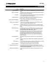
Actuator does not hold
consistent position-oscillates
or dithers
Varying position demand signal Ensure stable position demand at the actuator
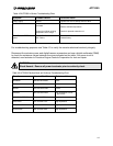
No position feedback Position feedback wires not
connected
No or low 120 VDC power
Actuator auto shut down
Ensure YELLOW and WHITE/YELLOW wires correctly
connected
Ensure 120VDC at Actuator
Upload Fault File- check for electronics or motor
windings over temperature faults.
Check for jammed extension rod
No motor current feedback Motor current wires not
connected
No or low 120 VDC power
Ensure BLUE and WHITE/BLUE wires correctly
connected
Actuator Operative- FAULT
alarm active
Open circuit
Internal FAULT
Ensure ORANGE and WHITE/ORANGE wires
correctly connected to Actuator
Upload Fault File to identify source of fault
Actuator Operative- OVER
TEMP alarm active
Open circuit
Electronics or Motor winding
temperature out of range
Ensure BLACK and WHITE/BLACK wires correctly
connected to Actuator
Reduce External ambient temperature
Check for jammed extension rod
RS232 Interface Inoperative Incorrect wiring
No or low 120 VDC power
COM1 not connected
Ensure WHITE/ORANGE/YELLOW,
WHITE/ORANGE/BLUE, WHITE/ORANGE/GREEN
wires correctly connected to Actuator and laptop PC.
Ensure 120 VDC Primary System Power at Actuator
Check laptop/PC com port
4-2