


ACT2000
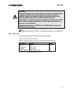
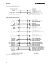
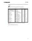
Table 3-4 shows the factory wiring and reference signals for the ACT2000 signal
harness.
Note: The serial wiring is segregated from the other wires.
Wire Color Function AWG Signals
WHITE/ORANGE/YELLOW Serial/RX In 20
± 12 V
WHITE/ORANGE/BLUE Serial/TX Out 20
± 12 V
WHITE/ORANGE/GREEN Serial Return 20 0 V
BLACK OVER TEMP Alarm 20 0 / 24 V
WHITE/BLACK OVER TEMP Alarm Return 20 0 V
ORANGE FAULT Alarm 20 0 / 24 V
WHITE/ORANGE FAULT Alarm Return 20 0 V
VIOLET RUN Command 20 0 / 24 V
WHITE/VIOLET RUN Command Return 20 0 V
GRAY RESET Command 20 0 / 24 V
WHITE/GRAY RESET Command Return 20 0 V
BROWN Position Demand 20 4 – 20mA
WHITE/BROWN Position Demand Return 20 0 V
YELLOW Position Feedback 20 4 – 20mA
WHITE/YELLOW Position Feedback RTN 20 0 V
BLUE Motor Current 20 4 – 20mA
WHITE/BLUE Motor Current RTN 20 0 V
Note: The serial Return is connected to the 120 V input return.
Table 3-4: ACT2000 Digital Harness Wire List
3-9