


ACT2000
2.2.1 Power
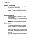
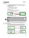
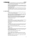
The ACT2000 operates on nominal 120 VDC, user-provided input voltage via the
four-wire power harness. Refer to Figure 2-2 for typical connection. Refer to
section 6 for specification values.
Primary power wires.
• +120 VDC is connected to the RED wire.
• The 120 VDC return wire is GREEN.
Redundant power wires:
• +120 VDC is connected to the WHITE/RED wire.
• 120 VDC return wire is WHITE/GREEN.
BATTERY/POWER SUPPLY
A
CTUATOR 120V INPUT
REVERSE VOLTAGE PROTECTION
PWR [RED]
PWR AUX [WHT/RED]
PWR RTN [GRN]
PWR RTN AUX [WHT/GRN]
FUSE
120VDC
Figure 2-2: Typical Power Connection
WARNING:
Shock Hazard – Both the 120 VDC power and auxiliary wires should be
connected. If only the primary power wires are connected, the 120 VDC
auxiliary power wires are electrically “hot” and must be insulated on the
ends.
Note: If a 120 VDC power supply is used, it must have at least 50,000 uF
internal capacitance. See Power Supply Requirements (Table 3-5).
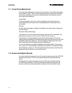
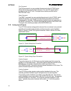
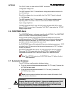
2.2.2 Discrete Commands
The ACT2000 accepts two discrete, two-wire external commands: RUN and
RESET. The commands are 24 VDC ON (High) and 0 VDC OFF (Low). Refer to
Figure 2-3 for typical connection. Refer to Section 6 for specification values.
CONTROLLER DISCRETE OUTPUT
A
CTUATOR DISCRETE INPUT
RUN RTN [WHT/VIO]
RESET RTN [WHT/GRY]
RUN [VIO]
RESET [GRY]
24Vdc
CONTROLLER DISCRETE OUTPUT
A
CTUATOR DISCRETE INPUT
RUN RTN [WHT/VIO]
RESET RTN [WHT/GRY]
RUN [VIO]
RESET [GRY]
Figure 2-3: Typical Discrete Command Connection
2-3