


ACT2000
List of Figures
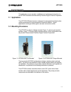
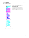
Figure 1-1: ACT2000 Pin Mounted....................................................................................1-1
Figure 1-2: ACT2000 Flange Mounted..............................................................................1-1
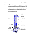
Figure 1-3: ACT2000 Cut-Away View ...............................................................................1-2
Figure 1-4: Typical Identification Plate...............................................................................1-5
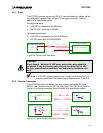
Figure 2-2: Typical Power Connection ..............................................................................2-3
Figure 2-3: Typical Discrete Command Connection.........................................................2-3
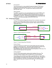
Figure 2-4: Typical Analog Input Connection....................................................................2-4
Figure 2-5: Typical Analog Output Connection.................................................................2-4
Figure 2-6: Typical Fault Alarm Connection......................................................................2-5
Figure 2-7: ACT2000 State Machine.................................................................................2-7
Figure 3-1: ACT2000-590P Envelope ...............................................................................3-2
Figure 3-2: ACT2000-200F Envelope ...............................................................................3-3
Figure 3-3: ACT2000 Wiring Diagram...............................................................................3-8
List of Tables
Table 2-1: ACT2000 Setup Parameters..........................................................................2-12
Table 3-1: Power Harness Recommended Wire Size......................................................3-5
Table 3-2: Digital Harness Recommended Wire Size......................................................3-6
Table 3-3: ACT2000 Power Harness Wire List.................................................................3-7
Table 3-4: ACT2000 Digital Harness Wire List .................................................................3-9
Table 3-5: Power Supply Requirements..........................................................................3-10
Table 4-1: ACT2000 Initial Installation Troubleshooting Chart.........................................4-2
Table 4-2: ACT2000 In-Service Troubleshooting Chart ...................................................4-3
Table 4-3: ACT2000 Electrical Hook-Up Continuity Troubleshooting Chart.….…...4-3
II