


DProPakII
58 MiLLennium GPSCard and Enclosures Guide to Installation & Operation
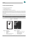
OPTIONAL MOUNTING BRACKET
The mounting kit includes the following materials:
•
four self-tapping screws (#10-16 x ½
″
LG)
•
two wood screws (#10 x ¾
″
LG)
•
four flat screws (M3 x 8, 90
°
countersink)
•
aluminum mounting plate (see Figure 24 for exact dimensions)
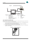
First, the mounting plate needs to be attached to the ProPak II enclosure. As shown in Figure 23, there are two channels
running the length of the bottom of the ProPak II enclosure. In each of these channels there are two rectangular nuts, held
in place by grub screws. These four nuts are factory-positioned so that the mounting plate can be attached to the ProPak
II enclosure using the four flat screws. Please ensure that the four flat screws are mounted from the countersunk side of
the mounting plate.
Once the plate has been attached to the ProPak II enclosure, the entire assembly can then be mounted onto a surface using
either the four self-tapping screws through the screw-mount holes, or the two wood screws through the quick-mount
holes.
Note: This mounting kit is not designed for use in high-dynamics or high-vibration environments. Contact NovAtel
Customer Service if your application requires the ProPak II to be mounted in these types of environments.
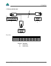
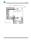
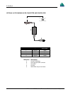
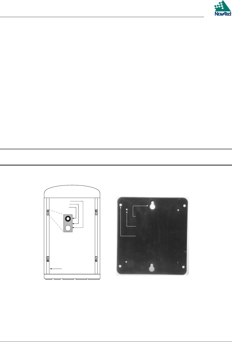
Figure 23 Mounting Bracket
5
6
7
1
2
3
4
8
9
Reference Description Reference Description
1
Thread for flat screw
6
Holes to mount plate to enclosure using
2
Rectangular nut flat screw
3
Grub screw
7
Holes to mount assembly to a surface
4
Channel using self-tapping screws
5
Quick-mount holes to mount assembly
8
Back of receiver enclosure
to surface using wood screws
9
Front of mounting plate