


C PowerPak II
MiLLennium GPSCard and Enclosures Guide to Installation & Operation 47
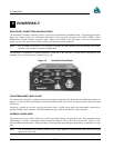
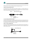
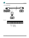
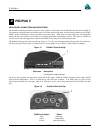
CONNECTION TO AN EXTERNAL OSCILLATOR
Connect the coaxial cable from the external oscillator output port to the Ext. Osc. input port (SMB male jack) on the front
panel of the PowerPak II. See the Optional External Oscillator section on Page 17.
INSTALLING THE MILLENNIUM
If you Purchased a MiLLennium and PowerPak II separately, installing the MiLLennium is described in the steps listed
below.
CAUTION !
•
Be sure that the power plug is disconnected from the PowerPak II before you attempt to remove the front panel.
•
Use the wrist strap to properly discharge static build-up before handling the printed circuit boards.
•
Use anti-static precautions whenever the PowerPak II is opened.
To open the PowerPak II:
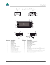
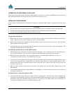
1. Remove the four corner screws from each of the front and back panels of the PowerPak II enclosure (refer back to
Figure 13Opening the PowerPak II Enclosure, Page 45 for more details).
2. Remove the rear panel; then, through this opening, push the power card forward as far as you can. This will expose
the back plane and the power board.
3. From the other end, grasp the exposed edges of the power board and gently pull until it comes out completely. The
front panel and back plane will be attached to it.
To attach the ground connector to the MiLLennium:
4. Find the ground wire which comes out of the backplane (refer back to Figure 13Opening the PowerPak II Enclosure,
Page 45 for more details). This wire will be connected to the MiLLennium by the end of this procedure.
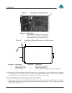
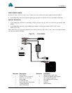
5. Remove the screw from the Pin 1 end of the 64-pin connector on the MiLLennium GPSCard (see Figure 16
Installing the Ground Connector on the MiLLennium, Page 48).
6. Insert this screw through the loop in the tongue of the spade connector plug which should be plugged into the socket
on the end of the ground wire. Reinsert the screw into the 64-pin connector, so that the spade connector plug is
attached to the solder side of the MiLLennium, points towards the 64-pin connector and angles away from the card
(see Figure 16, Page 48).
7. Slide the spade connector socket of the loose end of the ground wire, onto the spade connector plug on the
MiLLennium.
8. Insert the MiLLennium into the 64-pin connector on the backplane. It should be above the power card, and have the
ground wire attached to it.
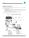
To attach the two coaxial interconnect cables:
9. The antenna RF interconnect cable is the shorter of the two coaxial cables. One end of this cable is attached to the
front panel of the PowerPak II enclosure; attach the right-angled SMB connector on the other end to the SMB male
jack (P201) on the edge of the MiLLennium (see Figure 15 Connections on the MiLLennium, Page 48 and Figure 16
Installing the Ground Connector on the MiLLennium, Page 48).