


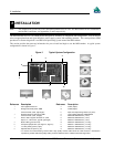
3 Installation
22 MiLLennium GPSCard and Enclosures Guide to Installation & Operation
CAUTION !
•
The P301 jumper plug must be jumpered to the external position (pins 2 and 3) before external LNA power is
connected to pin 4B of the 64-pin wire harness connector to prevent power from feeding back into the receiver.
•
Should it be necessary, due to an extended-length antenna cable, to supply external power to a GPSAntenna or to use
an optional in-line LNA amplifier, be careful not to exceed the voltage ratings of either the antenna or LNA.
•
No guarantee is made that the MiLLennium will meet its performance specifications if a non-NovAtel antenna is
used.
It is recommended that appropriate fuses or current limiting be incorporated as a safety precaution on all power lines
used. Use a sufficient gauge of wire to ensure that the voltage at the 64-pin connector is within the MiLLennium’s
requirements.
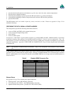
RS232C Communications
The MiLLennium is capable of communications in EIA RS232C serial data format via two ports, COM1 and COM2.
See Appendix B, Page 33 for data connections:
•
COM1
pins 7 - 11, A & B
•
COM2
pins 15 - 19, A & B
Each port has a ground connection, and supports the following signals:
•
Data Terminal Ready (DTR)
•
Clear To Send (CTS)
•
Transmitted Data (TXD)
•
Request To Send (RTS)
•
Received Data (RXD)
•
Data Set Ready (DSR)
•
Data Carrier Detect (DCD)
The port settings (bit rate, parity, etc.) are software-configurable. These are further described in Chapter 4.
Note: See Appendix B, Page 33 for further information on data communications characteristics.
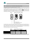
Strobe Signals
The MiLLennium has 5 TTL-compatible I/O strobe lines. See Appendix B, Page 33 for strobe signal connections:
•
Variable-Frequency (VARF) Output
Pin 21B
•
One Pulse per Second (PPS) Output
Pin 22B
•
Measure Output
Pin 23B
• Mark Input
Pin 24B
• Status Output
Pin 25B
Note: See Appendix B for further information on I/O strobe characteristics.