


DProPakII
54 MiLLennium GPSCard and Enclosures Guide to Installation & Operation
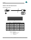
SERIAL DATA CABLES
Two serial data cables are supplied to connect the ProPak II to a PC or modem. They are described as follows:
•
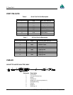
straight cable: 10-pin LEMO plug to 9-pin D-connector (DE9P plug); Appendix B contains wiring and pin-out
information on this cable. This is used to connect the ProPak II to a modem or radio transmitter to propagate
differential corrections. Its NovAtel part number is 01016383.
•
null-modem cable: 10-pin LEMO plug to 9-pin D-connector (DE9S socket); Appendix B contains wiring and pin-out
information on this cable. This is used to connect the ProPak II to a serial (RS232C) communication port on a
terminal or computer. Its NovAtel part number is 01016329.
The 10-pin plug on each cable can be plugged into either the COM1 or COM2 port on the ProPak II.
For field replacement of the LEMO connector, please consult Appendix G, REPLACEMENT PA, for a list of the
manufacturers’ part numbers.
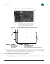
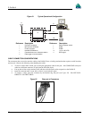
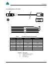
I/O STROBE PORT CABLE
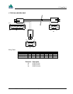
The I/O strobe lines can be accessed by inserting the 8 pin LEMO connector of the I/O strobe port cable (NovAtel part
number 01016330) into the I/O port. Appendix B contains wiring and pin-out information on this cable. The other end of
the cable is provided without a connector so that you can provide an application-specific one; the jacket insulation is cut
away slightly from the end but the insulation on each wire is intact. The Input/Output Strobes section of Appendix B,
MILLENNIUM TECHNICAL ,
ProPak II, Page 57 contains descriptions of each of the I/O strobes, along with their electrical specifications.
For field replacement of the LEMO connector, please consult Appendix E, REPLACEMENT PA, for a list of the
manufacturers’ part numbers.
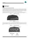
Note that the STATUS line is used to toggle the valid-position LED on the front end-cap between red (power on) and
green (valid position).
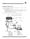
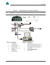
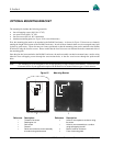
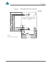
PROPAK II INSTALLATION
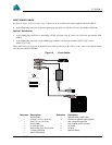
Installing the ProPak II is a straightforward process. As shown in Figure 20, Page 55 a minimum configuration is
established with the following set-up:
• Set up the GPSAntenna.
• Route and connect coaxial cable between the GPSAntenna and ProPak II.
• Connect an RS232C communication interface to one of the serial ports of the ProPak II. The supplied null
modem cables are intended for RS232C communications only.
• Connect the output of the optional power converter to the input power jack of the ProPak II.