


DProPakII
56 MiLLennium GPSCard and Enclosures Guide to Installation & Operation
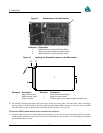
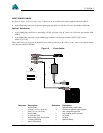
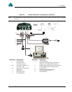
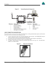
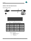
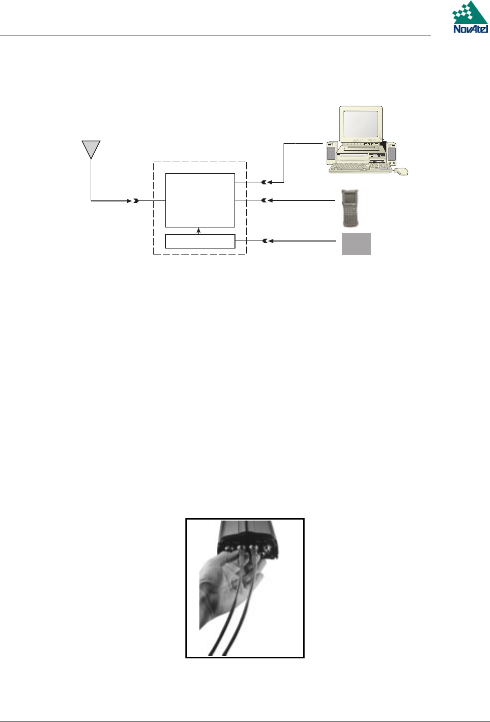
Figure 21 Typical Operational Configuration
1
2
3
4
5
8
9
10
11
6
7
Reference Description Reference Description
1
ProPak II enclosure
7
External power source
2
MiLLennium GPSCard
8
COM1
3
Power converter
9
COM2
4
NovAtel GPSAntenna
10
+10to+36VDC
5
Command source or reference station
11
GPS signal
6
Data logger or remote station
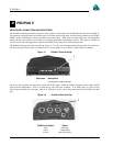
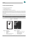
CABLE CONNECTION CONSIDERATIONS
The connectors that are used to mate the cables to the ProPak II have a locking mechanism that requires careful insertion
and removal. Observe the following when handling the cables.
•
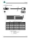
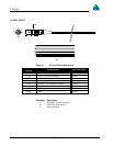
To insert a cable, make certain you are using the appropriate cable for the port – the COM1/COM2 serial port
cable has a different connector (10 pin) than the I/O cable (8 pin).
•
Line up the red dot on the connector shell with the red index mark on the receptacle on the ProPak II.
•
Insert the connector until it seats with a click; it is now locked in place.
•
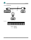
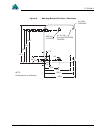
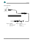
To remove a cable, grasp the connector by the knurled ring and pull (see Figure 22). DO NOT PULL
DIRECTLY ON THE CABLE.
Figure 22 Removal of Connectors