B MiLLennium Technical Specifications
40 MiLLennium GPSCard and Enclosures Guide to Installation & Operation
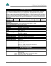
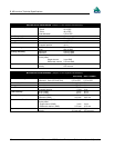
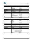
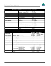
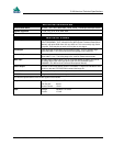
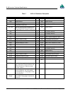
Table 5 64 Pin I/O Connector Description
Row B Descriptions Pin Row A Descriptions
GND Digital Ground 1 GND Digital Ground
+5V Input, power supply 2 +5V Input, power supply
* Reserved for future use 3 N/C
LNA_PWR Optional external power to antenna other
than a standard NovAtel GPSAntenna
(jumper plug P301 must be correctly set)
4 GND Digital Ground
N/C 5 * For factory use only
N/C 6 * For factory use only
N/C 7 GND Digital Ground
N/C 8 DTR1 Data Terminal Ready for COM 1
CTS1 Clear to Send for COM 1 9 TXD1 Transmitted Data for COM 1
RTS1 Request to Send for COM 1 10 RXD1 Received Data for COM 1
DSR1 Data Set Ready for COM 1 11 DCD1 Data Carrier Detected for COM 1
N/C 12 N/C
N/C 13 * For factory use only
N/C 14 * For factory use only
N/C 15 GND Digital Ground
N/C 16 DTR2 Data Terminal Ready for COM 2
CTS2 Clear to Send for COM 2 17 TXD2 Transmitted Data for COM 2
RTS2 Request to Send for COM 2 18 RXD2 Received Data for COM 2
DSR2 Data Set Ready for COM 2 19 DCD2 Data Carrier Detected for COM 2
N/C 20 N/C
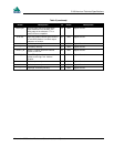
VARF Output Variable-frequency pulse train; normally
high, active low. The pulse width is from
100 ns to 6.55 ms. Frequency range:
0.15 Hz - 5 MHz.
21 GND Digital Ground
PPS Output Normally high, active low, 1 ms ± 50 ns
pulse is output at 1 Hz (± 50 ns when
clock steering on). Falling edge is used
as the reference.
22 GND Digital Ground
Measure
Output
Normally high, active low pulse is 1 ms ±
50 ns wide. Falling edge is used as the
reference.
23 GND Digital Ground


