


B MiLLennium Technical Specifications
MiLLennium GPSCard and Enclosures Guide to Installation & Operation 39
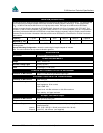
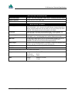
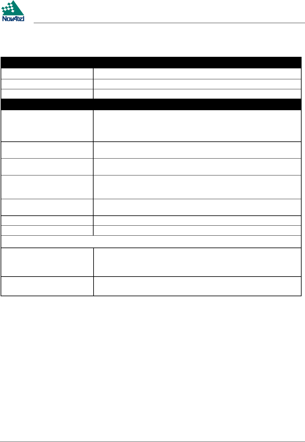
INPUT/OUTPUT DATA INTERFACE
Dual RS-232C Serial Bit rates: 300, 1200, 4800, 9600, 19200, 57600, 115200 bps (9600 bps default)
Signals supported TX, RX, RTS, CTS, DTR, DSR, DCD
Electrical format EIA RS232C Standard
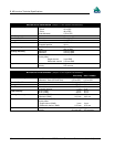
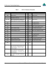
INPUT/OUTPUT STROBES
VARF Output A programmable variable-frequency output ranging from 0.15 Hz - 5 MHz (refer
to the FREQUENCY_OUT command in the
MiLLennium Command Descriptions
Manual
), with pulse width from 100 ns to 6.55 ms. This is a normally high, active
low pulse. There may be as much as 50 ns jitter on this signal.
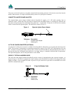
PPS Output A one-pulse-per-second time synchronization output. This is a normally high,
active low pulse (1 ms ± 50 ns) where the falling edge is the reference.
Measure Output Periodic output at the measurement rate, normally high, active low where the
pulse width is 1 ms. The falling edge is the receiver measurement strobe.
Mark Input An input mark (negative pulse > 55 ns), time tags output log data to the time of
the falling edge of the mark input pulse (refer to LOG command syntax –
ONMARK in the
MiLLennium Command Descriptions Manual
).
Status Output Indicates a valid GPS position solution is available. A high level indicates a valid
solution or that the FIX POSITION command has been set.
RESETOUT Polarity- positive pulse ; 140 ms ≤ pulse duration ≤ 280 ms
\RESETIN A high to low transition causes a system reset.
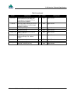
The electrical specifications of the strobe signals are as follows:
Output Voltage: Standard TTL levels
Sink Current:
Source Current:
64 mA
15 mA
Input Voltage: Standard TTL levels
Current: ≤ 5mA