


DProPakII
52 MiLLennium GPSCard and Enclosures Guide to Installation & Operation
DPROPAKII
D PROPAK II
ENCLOSURE, CONNECTORS AND INDICATORS
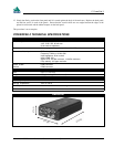
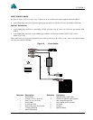
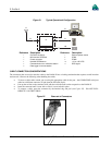
The ProPak II mounting enclosure provides a more protective environment for the MiLLennium than the PowerPak II.
The mounting enclosure houses the internal power card, interconnect back plane, and front panel connections for COM1,
COM2, strobes, GPSAntenna, external oscillator, and power input. With shock resistant design and environmentally
sealed end-caps and connectors, the ProPak II is designed with harsh environments in mind. This makes it suitable for
avionics, naval, and other applications where the PowerPak II does not provide sufficient protection.
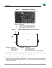
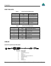
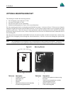
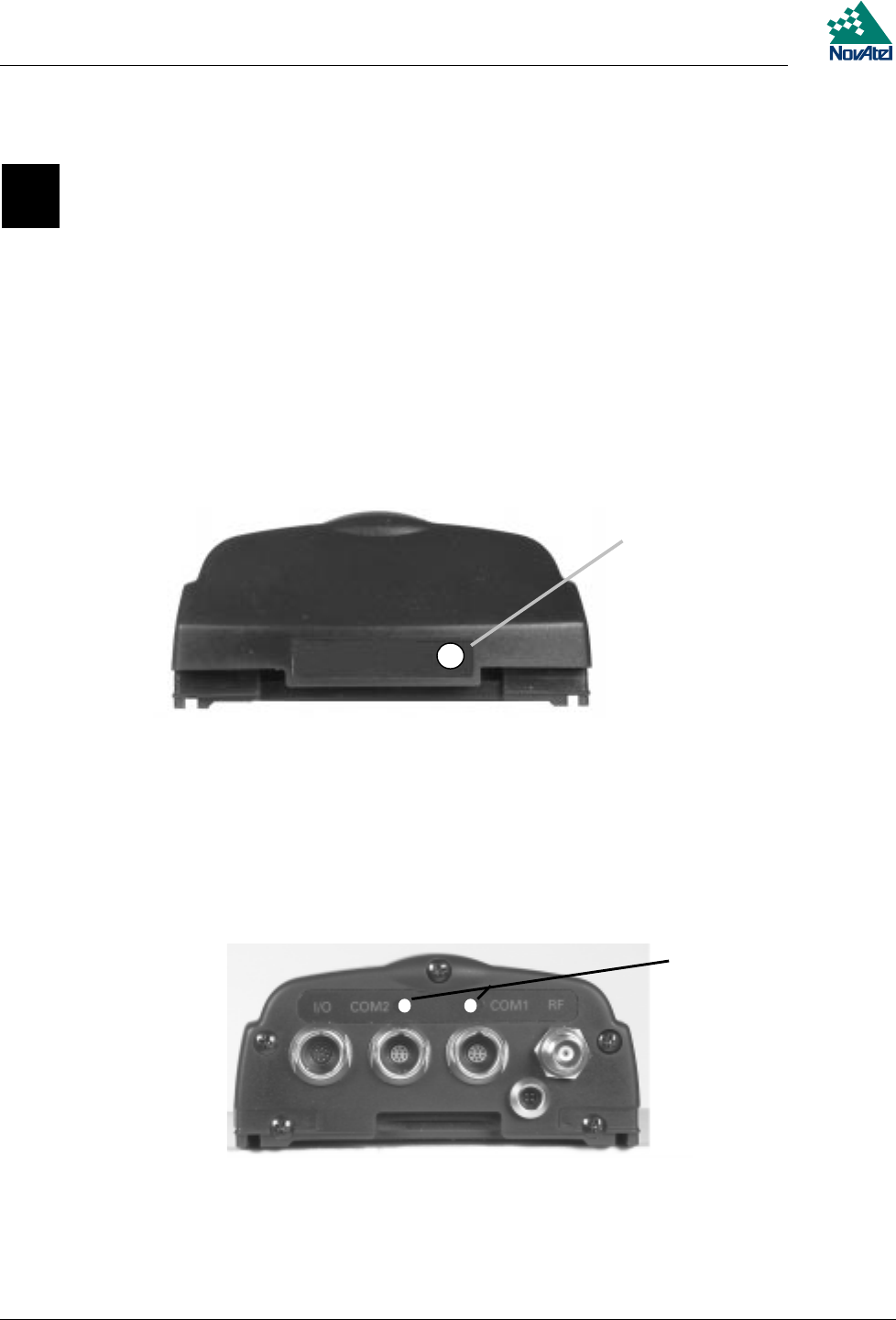
The ProPak II features front and rear end-caps (Figures 17 & 18), each with appropriate indicator lights and connectors.
The front end-cap indicator glows red when power is on, and changes to green when a valid position is computed.
Figure 17 ProPak II Front End-Cap
ProPak II
ProPakII
Reference Description
1 Power/position validity indicator
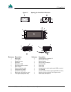
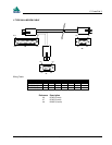
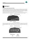
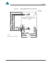
On the rear end-cap there are connections for the I/O strobe signals, COM1 & COM2 serial ports, power input, and RF
input from the GPSAntenna. There is an LED above each serial port connector. If an LED glows red, data is being
received by the ProPak II on that port, while if an LED glows green, data is being transmitted by the ProPak II on that
port.
Figure 18 ProPak II Rear End-Cap
COM Port Indicator
1
Status
Red Receiving
Green Transmitting
Yellow Both of the above
1
1